D877 MGB Rev01 HE250.docx
27/50
The electronic board detects the necessary conditions and activates the output solenoid ERS, which controls
the valve VSC.
The card goes in error (error code = 19, DSP = E3) in one of the following streams situations:
-
Incorrect coil power consumption solenoid valvole ERS
-
Valve position VNR not on Zero
-
Non-opening sensing valve VSC
-
Power input ERS Solenoid valve for more than 12 s.
3.5
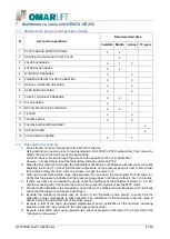
Verification of the periodic self-monitoring function of redundancy
Before proceeding, check the manual of the control panel steps to be taken, to perform a verification test of
the descent valves
3.5.1
Check the VSC valve sealing
Perform the test as indicated on the instructions of the control panel.
When solenoid valve ERN activated, on DSP of the board appears the indication A1.
During the solenoid ERN activation, activate the manual emergency device until the intervention of the
relevelling.
If at the end of the relevelling, the control panel repeats the test with the solenoid activation ERN (DSP = A1 ),
cause, as previously,anewrelevelling. The control panel must, at this point, lock the elevator and obtain service
for its release.
3.5.2
Check the VNR valve sealing
Perform the test as indicated on the instructions of the control panel.
When solenoid valve ERN activated, on DSP of the board appears the indication A1.
Wait the end of the activation of the solenoid valve and the ERN and the following pause time when it appears
on the board, the indication A2.
When solenoid valve ERS activated, on DSP of the board ,appears the indication A3.
Durante l'attivazione dell'elettrovalvola ERS azionare il dispositivo di emergenza manuale sino all'intervento
del ripescaggio.
If at the end of the relevelling, the control panel repeats the test with the solenoid activation ERS (DSP = A3 ),
cause, as previously,anewrelevelling.
The control panel must, at this point, lock the elevator and obtain service for its release.
3.6
Self-control of monitoring PNP1 signal
An automatic control of PNP1 signal could be performed, alternatively or additionally to the functional check
of redundancy during a downward travel (point 2.0), to check, for each maneuver, including releveling, the
correct sequence of opening and closing of the valves hydraulic participating at the block of the cabin.
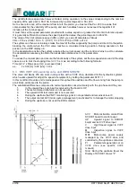
The monitoring must be carried by controlling the timing of PNP1 following a change of state of the switching
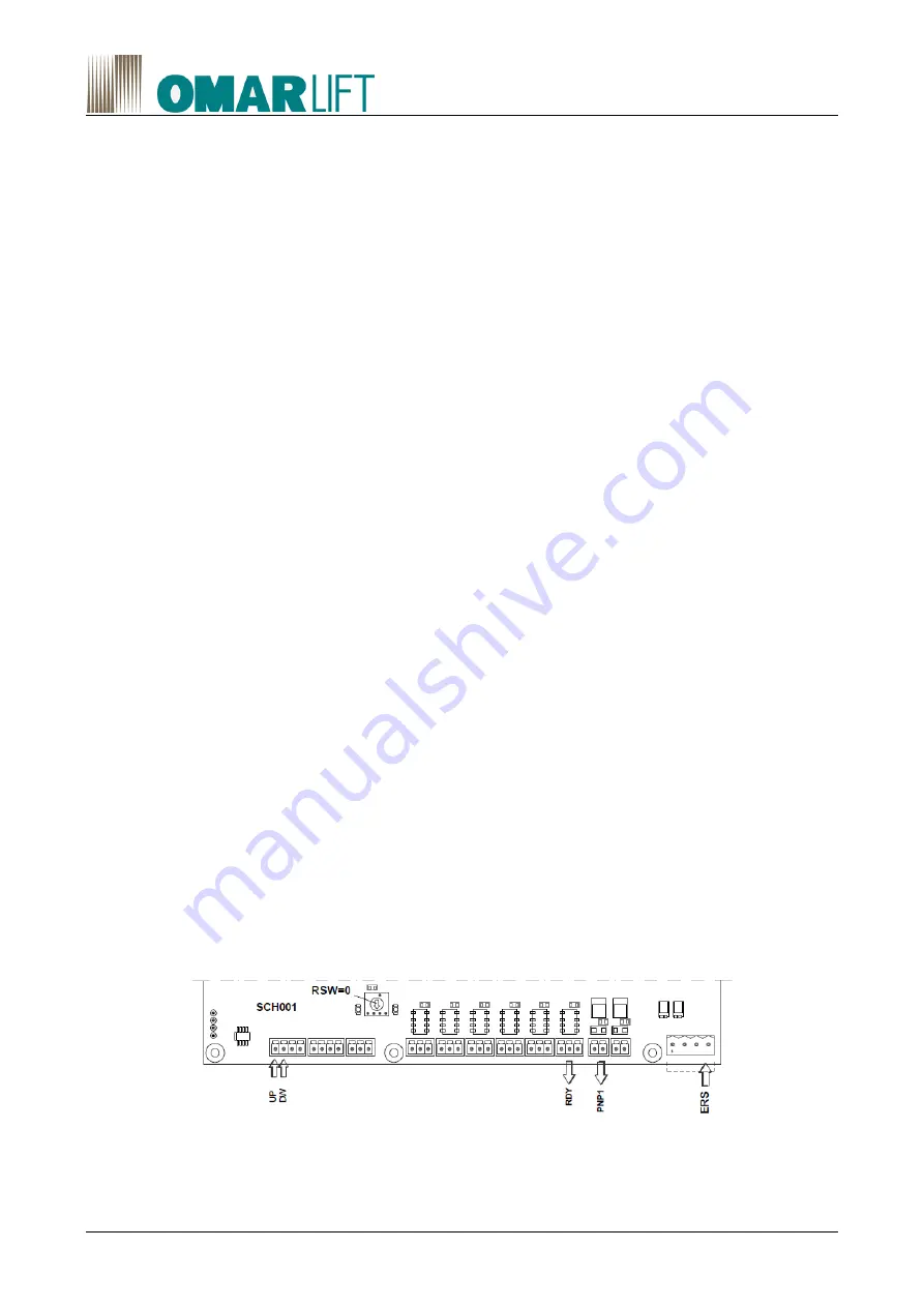
signal, corresponding, on the electronic board SCH001, the entrance solenoid ERS + the up signal or down.
The framework must be able to detect two different errors:
Error 1: when the maneuver signal switches from high to low level, the PNP1 signal switches to the high state
within a time from 0.1s to 1s.
Se le tempistiche non sono rispettate deve essere generato un allarme da gestire come previsto dalla norma.
Error 2: when the maneuver signal goes from low to high level, the PNP1 signal switches to the low state within
0.1s. If the deadlines are not met an alarm to manage, as required by the standard ,to be generated.
Note: The schedule in the PNP1 signal handling are compatible with those used in the monitoring of the valves
to SMA iValve Bucher Group.
Involved signals:
Ready signal RDY from the card to the waiting framework commands.
Section 3.7 describes the monitoring of PNP1 signal check cycle.
Section 3.8 describes the verification of self-monitoring provided for at point 6.3.13 of EN81-20 regulation.


