background image

CAP.3

SICUREZZA

É estremamente importante leggere questo capitolo attenta-
mente ed in ogni sua parte poichè contiene importanti infor-
mazioni sui rischi che operatore e manutentore possono cor-
rere in caso di un uso errato del ponte sollevatore.
Nel testo che segue troverete chiare spiegazioni su alcune si-
tuazioni di rischio o pericolo che si possono verificare durante
l’uso e la manutenzione del sollevatore, sui dispositivi di sicu-
rezza adottati e sul loro uso corretto, sui rischi residui e sui
comportamenti da tenere (precauzioni generali e specifiche
per eliminarli o neutralizzarli).

I

ATTENZIONE:

I sollevator sono stati progettati e costruiti per il
sollevamento e lo stazionamento in quota dei vei-
coli in ambiente chiuso. Ogni altro uso non è con-
sentito ed in particolare essi non sono idonei per
operazioni di:

- lavaggio e verniciatura;
- ponteggio o sollevamento di persone;
- pressa per schiacciare;
- montacarichi;
- CRIC per sollevare o cambiare ruote.

Il costruttore non risponde di alcun danno a per-
sone, veicoli od oggetti causati dall’uso improprio
o non consentito dei ponti sollevatori
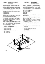
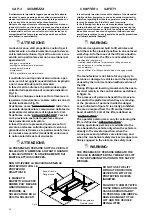
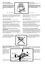
In fase di salita o discesa l’operatore deve agire
soltanto dalla postazione di comando indicata in
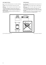
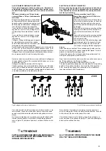
Fig.16.
É vietato a chiunque sostare sotto le traverse e/o
le pedane in movimento o sostare entro la zona di
rischio indicata in Fig.16.
Si definisce come “ZONA DI RISCHIO” tutta l’area
occupata dal sollevatore comprensiva della fascia
perimetrale del sollevatore di larghezza 1÷2 mt.
Si definisce come “ZONA OPERATORE” l’area in
cui è prevista la sosta dell’operatore solo per
l’azionamento del sollevatore.
In fase di lavoro la presenza di persone sotto il
veicolo è ammessa soltanto quando il veicolo è
già sollevato, le traverse e le pedane sono ferme e
le sicurezze meccaniche (martelletti) sono inseri-
te nelle asole delle aste di sicurezza.

I

ATTENZIONE:

LA PRESENZA DI PERSONE SOTTO IL VEICOLO
SOLLEVATO E’ AMMESSA SOLTANTO QUANDO
IL SOLLEVATORE E’ IN STAZIONAMENTO SUI
MARTELLETTI DI SICUREZZA.

NON UTILIZZARE LA MACCHINA SENZA LE
PROTEZIONI O CON LE
PROTEZIONI
DISATTIVATE.

IL MANCATO
RISPETTO DI QUESTE
NORME PUO’ RECARE
GRAVI DANNI ALLE
PERSONE, AL
SOLLEVATORE ED AI
VEICOLI SOLLEVATI.

Fig.16

CHAPTER 3

SAFETY

It is extremely important to read this chapter of the manual ca-
refully and from beginning to end as it contains important in-
formation regarding the risks the operator or maintenance fit-
ter may be exposed to if the lift is used incorrectly.
In the following text there are clear explanations regarding
certain situations of risk or danger that may arise during the
operation or maintenance of the lift, the safety devices instal-
led and the correct use of such systems, residual risks and
operative procedures to use (general and specific precautions
to eliminate potential hazards).

I

WARNING:

Lifts are designed and built to lift vehicles and
hold them in the elevated position in an enclosed
workshop. All other uses of the lifts are unautho-
rised. In particular, the lifts are not suitable for:

- washing and respray work;
- creating raised platforms for personnel or lifting personnel;
- use as a press for crushing purposes;
- use as elevator;
- use as a lift jack for lifting vehicle bodies or changing wheels.

The manufacturer is not liable for any injury to
persons or damage to vehicles and other property
caused by the incorrect and unauthorised use of
the lifts.
During lifting and lowering movements the opera-
tor must remain in the control station as defined
in figure 16.
The presence of persons beneath the cross-pie-
ces and/or the platforms when they are moving,
or the presence of persons inside the danger
zone indicated in figure 16 is strictly prohibited.
The area occupied from the lift and perimetral
band of width 1÷2 mt of the lift are defined as
"DANGER ZONE".
The operator parking area, only for actioning the
lift, is defined as "OPERATOR ZONE".
During operations persons are admitted to the
area beneath the vehicle only when the vehicle is
already in the elevated position, when the
cross-pieces and platforms are stationary, and
when the mechanical safety devices (wedges) are
firmly engaged in the slots on the safety rods.

I

WARNING:

THE PRESENCE OF PERSONS BENEATH THE
VEHICLE IS PERMITTED ONLY WHEN THE LIFT
IS IN THE PARKING POSITION ON THE SAFETY
WEDGES.

DO NOT USE THE LIFT
WITHOUT PROTECTION
DEVICES OR WITH THE
PROTECTION DEVICES
INHIBITED.

FAILURE TO COMPLY WITH
THESE REGULATIONS CAN
CAUSE SERIOUS INJURY
TO PERSONS, AND IRREPA-
RABLE DAMAGE TO THE
LIFT AND THE VEHICLE
BEING LIFTED.

16

Zona di rischio
Danger zone

Zona operatore
Operator zone

Summary of Contents for 528C

Page 1: ...I PONTE SOLLEVATORE A 4 COLONNE GB 4 POST LIFT 528C...

Page 2: ......

Page 3: ...I ITALY Telefono 444 436199 Telefax 444 436208 1 Emissione 02 04 2008 CENTRO DI ASSISTENZA AUTORIZZATO Rev 3 23 07 2009 Instruction manual for using and maintaining ELECTRO HYDRAULIC LIFTS FOR VEHICLE...

Page 4: ...rimedi Pag 38 Appendice A Informazioni particolari Pag 39 Appendice B Parti di ricambio Pag 39 Contents Packing transport and storage Page 3 Introduction Page 4 Chapter 1 Description of the machine Pa...

Page 5: ...ando regge legacci o altri mezzi idonei Nei cassoni dei camion nei container nei vagoni ferroviari si possono impilare al massimo due pacchi purch vengano reggiati tra loro e assicurati contro la cadu...

Page 6: ...e costruiti rispettando quanto segue LEGGI Direttive europee 98 37 CE 2004 108 CE 2006 95 CE NORME TECNICHE Norme europee EN 1493 EN 292 1 EN 292 2 IMPIANTO ELETTRICO UNI EN 60204 CEI 64 8 OPENING THE...

Page 7: ...so le diciture operatore e manutentore il cui significato il seguente OPERATORE persona addetta all uso del sollevatore MANUTENTORE persona addetta alla manutenzione ordinaria del sollevatore Lifting...

Page 8: ...riore sinistra 3 colonna posteriore sinistra 4 colonna posteriore destra 5 traversa lato comando traversa anteriore 6 traversa traversa posteriore 7 pedana destra fissa 8 pedana sinistra mobile Fig 3...

Page 9: ...sibile di mandata olio 10 un tubo flessibile per il recupero dell olio 11 NOTA Il tubo di mandata olio 10 pu tro varsi in pressione Il tubo di recupero olio 11 non mai in pressione Fig 6 Pannello di c...

Page 10: ...blocco 2 il giogo di attacco 3 delle funi di acciaio due gruppi pulegge di rinvio 4 delle funi Fig 10 Interno pedana fissa MOVABLE STRUCTURE The movable structure consist of two cross pieces and two...

Page 11: ...ore stesso Fig 11 Dimensioni ed ingombri POMPA Tipo 20 Modello 10A7 4X348N Cilindrata 7 4 cm3 g Taratura valvola di massima 160 bar CHAPTER 2 SPECIFICATIONS CAPACITY 8000 kg 78400 N Max vehicle liftin...

Page 12: ...he hydraulic power unit i e the various components of the pump that convert the rotary motion of the motor into fluid pressure for the hydraulic circuit Figure 12 Fig 12 Hydraulic power units OIL The...

Page 13: ...SCHEMI ELETTRICI ED OLEODINAMICI WIRING DIAGRAMS AND HYDRAULIC 11...

Page 14: ...alita Lifting relay Integrato nella scheda Integrate in the electric board 1 KA4 Rel primario trasformatore Primary transformer relay FINDER 55 34 9 024 0040 1 KT1 Rel TR1 elettromagneti Relay TR1 ele...

Page 15: ...Micro funi Cable micro switch Marrone Braun Blu Blau Marrone Braun Blu Blau Micro funi Cable micro switch Micro funi Cable micro switch Micro funi Cable micro switch Elettromagnete Electromagnet Gial...

Page 16: ...Relief valve 5 Throttle valve 6 Motor 7 Pump 8 Filter 9 Reservoir 14 Motore protezione termica motore Motor and thermal switch 8 9 Elettromagneti Electromagnet Microinterruttori fune and ON OFF switch...

Page 17: ...I DEI VEICOLI DA SOLLEVARE Fig 14 Ripartizione pesi A Fig 14 Weight distribution A TYPES OF VEHICLES SUITABLE FOR BEING LIFTED AND OVERALL DIMENSIONS Lifts are suitable for virtually all vehicles with...

Page 18: ...16 CHAPTER 3 SAFETY It is extremely important to read this chapter of the manual ca refully and from beginning to end as it contains important in formation regarding the risks the operator or maintena...

Page 19: ...Fig 17 Spostamento longitudinale e protezione GENERAL PRECAUTIONS The operator and the maintenance fitter are required to observe the prescriptions of safety regulation in force in the country of in s...

Page 20: ...rante il sollevamento e lo stazionamento Fig 19 Fig 19 Veicolo caricato correttamente SIDE MOVEMENTS For optimal personal safety and safety of vehicles observe the fol lowing regulations do not enter...

Page 21: ...ttore Pos 4 Fig 23 situato sulle funi all inter no della traversa interrompe l alimentazione al motore Fig 23 Martelletto di sicurezza e fine corsa POTENTIAL RISKS DURING LIFTING The following safety...

Page 22: ...o essersi accertato che nessuna persona sia nella zona di rischio Fig 16 26 27 Fig 26 Fig 26 RISKS FOR PERSONNEL This heading illustrates potential risks for the operator maintenan ce fitter or any ot...

Page 23: ...lla discesa Fig 31 Rischio di allentamento delle funi RISK OF IMPACT Caused by the parts of the lift or the vehicle that are positioned at head height When due to operational reasons the lift is stopp...

Page 24: ...d by lubricant contamination of the flo or around the lift fig 32 THE AREA BENEATH AND IMMEDIATELY SURROUNDING THE LIFT AND ALSO THE PLATFORMS MUST BE KEPT CLEAN Re move any oil spills immediately Fig...

Page 25: ...tre essere piano e ben livellato Max 10 mm sul livellamento Fig 36 Carichi sulle fondazioni CHAPTER 4 INSTALLATION THE FOLLOWING OPERATIONS MUST BE PER FORMED EXCLUSIVELY BY SPECIALISED TECH NICAL STA...

Page 26: ...8 Le misure indicate sono tassative con tolleranze ammesse su allineamento 1 mm su squadratura 2 mm Fig 38 Tracciatura INSTALLING WITH EXPANSION ANCHORS Example of installation on industrial floor in...

Page 27: ...e pedane quindi serrare a fondo le viti 15 di fissaggio delle pe dane 7 8 ASSEMBLY IWARNING UNAUTHORISED PERSONS MUST NOT BE AD MITTED DURING ASSEMBLY OPERATIONS ASSEMBLY OF MOVABLE STRUCTURE PLATFORM...

Page 28: ...Fig 40 Fig 40 26 B K X K X Fune K Colonne 1 3 Fune X Colonne 2 4 Cable K Posts 1 3 Cable X Posts 2 4...

Page 29: ...ola di disce sa 15 al finecorsa salita 16 e al finecorsa discesa 50 vedi schemi elettrici Fig 42 Preparazione colonna 1 POST ASSEMBLY Remove the safety rods 12 from the top of the posts 1 2 3 4 as sho...

Page 30: ...fermo il particolare 5 Fig 46 con una chiave 6 Fig 46a Fig 46 Allacciamento impianto idraulico Fig 46 Hydraulic system Position the posts at the end of the cross pieces pos 5 6 fig 39 obser ving the n...

Page 31: ...delle fasi agganciate come in figura 47 richiudere il quadro e verificare il senso di rota zione IATTENZIONE TUTTE LE OPERAZIONI INDICATE SOPRA DEVO NO ESSERE ESEGUITE UNICAMENTE DA PER SONALE SPECIAL...

Page 32: ...chiave dinamometrica e controllare che abbiano tutte la stessa coppi adi serrag gio Fig 51 Preregistrazione funi Fig 52 Before making any manoeuvres 1 Check the fluid level and fill if necessary usin...

Page 33: ...ghi 65mm tipo FISCHER SLM 10 o HILTI HB M10 Serrare le viti con chiave dinamometri ca tarata a 35 Nm Fig 55 Fissaggio delle colonne SECURING THE POSTS TO THE GROUND Lower the platform see operating in...

Page 34: ...ne da ripe ter si dopo 1 o 2 settimane dalla messa in servizio del solleva tore Fig 57 Registrazione funi INSTALLING THE VEHICLE RAMPS AND THE WHEEL STOPS The vehicle ramps pos 41 fig 56 and the wheel...

Page 35: ...prove a carico effettuare un controllo visivo della macchina e riverificare il serraggio della bulloneria PRELIMINARY TESTS AND INSPECTIONS BEFORE STARTING MECHANICAL CHECKS Check that the cables are...

Page 36: ...ale caduta del vei colo sempre assicurata dal martelletto comandato dal sensore allentamento funi CHAPTER 5 OPERATING PRINCIPLES AND USE The lift operator controls are MAIN SWITCH QS Fig 59 POSITION 0...

Page 37: ...tura disegni esplosi con i dati necessari per l ordinazione dei ricambi elenco dei possibili casi di malfunzionamento e delle soluzioni con sigliate capitolo 7 del manuale CHAPTER 6 MAINTENANCE IWARNI...

Page 38: ...e o le aste 5 SUPERFICIE SUPERIORE DELLE TRAVERSE Mantenere un leggero velo di grasso per facilitare lo scorrimen to della pedana mobile PERIODIC MAINTENANCE SCHEDULE To keep the lift working at optim...

Page 39: ...re le superfici dalla sporcizia portata dal veicolo ghiaia ter ra catrame sale ed altro Il rivestimento costituito da smalto a polvere termoindurente e pu essere trattato solo con prodotti a base neut...

Page 40: ...are voltaggio La pompa della centra lina rumorosa Olio contaminato Montaggio errato Sostituire olio Chiamare Servizio Assistenza Perdita oilo dal cilindro idraulico Guarnizioni danneggia te Sporcizia...

Page 41: ...colorazioni Per avere il codice preciso sostituire le X con il codice colore riportato nella tabellina sottostante indicare la quantit richiesta La richiesta deve essere fatta al rivenditore autorizza...

Page 42: ...COLONNE POSTS S ULEN COLONNES COLUMNAS...

Page 43: ...TRAVERSE CROSSBEAMS TRAVERSE TRAVERSES TRAVERSA OS...

Page 44: ...PEDANE PLATFORMS FAHRSCHIENE CHEMINS DE ROULEMENT PLATAFORMAS...

Page 45: ...CILINDRO CYLINDER ZYLINDER V RIN CILINDRO...

Page 46: ...CENTRALINA OLEODINAMICA K3 OLEODYNAMIC CONTROL UNIT K3 OELDYNAMISCHES SCHALTGEH USE K3 CENTRALE HYDRAULIQUE K3 CENTRALITA OLEODIN MICA K3...

Page 47: ...QUADRO ELETTRICO TRIFASE CONTROL PANEL SCHALTTAFEL DREHSTROM COFFRET LECTRIQUE CUADRO ELECTRICO...

Page 48: ...5739 SCREW TE M10 X 25 SCHRAUBE TE M10 X 25 VIS TH M10 X 25 TORNILLO TE M10X25 B5007 RONDELLA P 10 X 30 UNI 6593 WASHER 10 X 30 UNI 6593 UNTERLEGSCHEIBE 10 X 30 UNI 6593 RONDELLE PLATE 10 X 30 UNI 659...

Page 49: ...TH 2 POLI T L C CONTROL SIDE CROSSPIECE 2 POLE TERMINAL BOARD KLEMMLEISTE MAMMUTH 2 POLE BORNIER MAMMUTH 2 P LES POUR TRAVERSE ARRI RE JUEGO TERMINALES MAMMUTH 2 POLOS T L C B5154 COPIGLIA 3X40 UNI 13...

Page 50: ...TELLETTO TOP SPRING FOR RETURN OBEREFEDER RESSORT SUPERIEUR DE RAPPEL MUELLE SUPERIOR B5415 PERNO ANTISCARRUCOLAM D16X128 PIN STIFT AXE PERNO B5418 BOBINA 24V 50 60HZ CONNETTORE COIL SPULE BOBINE BOBI...

Page 51: ...E FOR BEAM PAD PLATTE FUR GLEITSCHUH ZYLINDERZUGSEIL LAME POUR PATIN PALONNIER HOJA POR PAT N YUGO B5885XX KIT RAMPA SALITA RISE RAMP KIT KIT AUFFAHRRAMPE KIT RAMPE DE MONT E KIT RAMPA DE ACCESO B5930...

Page 52: ...ELLE 10 5X21 ARANDELA PLANA 10 5X21 C0099 VITE TE 6X20 8 8 UNI 5739 SCREW M6X20 8 8 SCHRAUBE M6X20 8 8 VIS TH M6 X 20 UNI 5739 TORNILLO TE M6X20 UNI 5739 C0100 RONDELLA 8 4X17 UNI 6592 WASHER 8 4X17 U...

Page 53: ...on la presente dichiariamo che il ponte sollevatore modello d clare par la presente que le pont elevateur mod le hereby we declare that the lift model hiermit erkl ren wir da Die Hebeb hne Modell por...

Reviews: