background image

                  Construction Manual 

www.oldschoolmodels.com 

Page 7

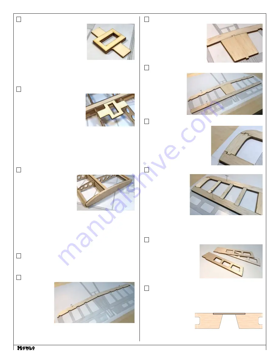
Step 26 - Wing Assembly (aileron servo mount)

Cut into LP4 are the aileron servo 

mounts. However there are two slightly 

different sizes to help accommodate 

the different brands servo sizes.

You’ll need one SM1 and one SM2 for 

each aileron mount. The pieces that 

are slightly larger are designed with 

the etched circle.

Glue one SM2 to SM1 as shown here - making sure both pieces 

either have an etched circle, or they both don’t (matched pairs).

Now do this again so you’ll have two matching aileron mounts.

Step 27 - Wing Assembly (aileron servo mount)

The aileron mount you just assembled 

in the previous step is now glued into 

place on the bottom of the wing, as 

shown here.

Note that if you’re using the slightly 

large SM1/SM2 pieces, it will only 

properly fit when the longer edge 

(designated by the etched circle) is orientated towards the trailing 

edge of the wing.

Also note that SM1 should be flush with the wing’s surface, with 

SM2 orientated inside the wing. (Refer to the photo.)

When satisfied with the fit and orientation, securely glue both 

aileron mounts in position.

Step 28 - Wing Assembly (Tip)

Locate both of the TIP pieces 

from BPTIP.

These are the wing tips and are 

glued into place, up against the 

outer R5 tip ribs.

Make sure each R5 is sanded flat 

with no extra wood protruding, 

then glue one TIP to each end.

You’ll need to make sure they are properly positioned as there 

isn’t a guide to aid in this step. Also, these TIP pieces are slightly 

oversized to give a bit of “wiggle-room”.

This completes assembly of the Mambo wing.

Now it’s time to start construction of the tail surfaces.

Prepare your work area

Now tape the horizontal stabilizer plan and a fresh piece of waxed 

paper on your building board. 

Step 29 - Horizontal Stab Assembly (S1)

Locate both S1’s 

from BP1. These 

are glued on top of 

each other to form 

a thicker S1. Make 

sure they are exactly 

aligned with each 

other when gluing 

them together.

Then pin them in place over the plan as shown here.

Step 30 - Horizontal Stab Assembly (S2)

Locate both S2’s from BP1. These 

are glued together to form a 

thicker S2, then glued to the 

center of S1, as shown here.

Step 31 - Horizontal Stab Assembly (S3)

Locate both S3’s from 

BP1. These are glued 

together to form a 

thicker S3, then glued 

to the S2, as shown 

here.

Step 32 - Horizontal Stab Assembly (S4)

Locate four S4’s from BP6 and BP7. 

These are glued together to make a 

pair of matching, thicker S4’s.

Then these S4’s are glue in place as 

the stab’s tips as shown here - one 

each end of the horizontal stab.

Step 33 - Horizontal Stab Assembly (S5, S6, and S7)

Locate four S5’s, four 

S6’s and four S7’s from 

BP1.

Glue two S5’s together 

to make a thicker S5, 

then do the same to 

make a matching pair 

of S5’s. Do the same for 

the S6’s and S7’s.

These are now glued in place as shown, making sure they are firmly 

seated in the pre-cut notches in S1 and S3.

Step 34 - Elevator Assembly (E1)

Locate four E1’s from BP1. 

Glue two E1’s (perfectly 

aligned on top of each other )

to form a thicker E1, then do 

the same for the remaining 

E1’s. This will give you the left 

and right elevator halves.

Step 35 - Elevator Assembly (joiner) 

Locate the 4” length of 3/32” dowel to create the elevator joiner. 

Measure and trim it to the length as shown on the plans - roughly 

3-1/4”.

Pin both elevator halves in 

position, making sure they 

are perfectly aligned with 

each other, then securely 

glue the elevator joiner 

dowel place.

Summary of Contents for Mambo

Page 1: ...at is in first class condition a correctly sized power system and components electronics batteries wheels etc throughout the building process You must correctly install all R C and other components so...

Page 2: ...sheet 1 BP9 laser cut 3 32 x 4 x 11 5 sheet 2 BP10 laser cut 3 32 x 4 x 24 sheet 1 BP11 laser cut 1 16 x 4 x 24 sheet 1 BP12 laser cut 1 16 x 4 x 24 sheet 1 BPTIP laser cut 1 4 x 4 x 9 sheet 1 3 32 x...

Page 3: ...ok a little different in some steps Online Supplementary Photos We realize that the smaller black and white photos in this manual might not show some of the steps as clearly as you might want So we ve...

Page 4: ...hould face R2 and be at the top as shown here Make sure it is perpendicular to R3 then glue in position Step 8 Wing Assembly WH4 and WH5 Locate one WH4 and one WH5 from LP1 First position WH4 into R3...

Page 5: ...is firmly seated while the glue cures Also make sure to remove any excess epoxy that may drip on the face of R1 Epoxy is easier to clean off before it cures by using a paper towel lightly soaked in a...

Page 6: ...on Measure and cut two 2 1 4 pieces Round both ends of both pieces and set them aside Now locate DG from LP1 and tape in place to the rear of the wing right in the center use the pre etched DG center...

Page 7: ...on of the tail surfaces Prepare your work area Now tape the horizontal stabilizer plan and a fresh piece of waxed paper on your building board Step 29 Horizontal Stab Assembly S1 Locate both S1 s from...

Page 8: ...TR1 has an etched circle on the top surface at the front edge Since you re using the Apprentice motor and motor mount hold F3 as shown top up on the building board then slip TR1 in at an angle making...

Page 9: ...place Take care that these pieces are orientated the right way when glued to FS2 When correct both LG2 s will face each other and the tabs of LG1 will be firmly seated in FS2 Step 42 Fuselage Assembl...

Page 10: ...F2 to obtain a secure fit F2 needs to be flush against the front of TR1 and the tabs from both fuselage sides need to be inserted into the pre cut slots in F2 When satisfied on how these pieces go to...

Page 11: ...e Assembly rear cap Back when you made the wings the leading edge was created from 5 16 square stock Use a piece of this stock to form the rear fuselage cap This piece will fit between the fuselage si...

Page 12: ...ach the stab in place Using scrap 3 16 square balsa cut two pieces roughly 3 in long From the underside of the fuse glue one of the strips in on each side where the fuselage and stab join this will st...

Page 13: ...unding the corners if you d like Step 74 Elevator Slot For the most of the Mambo build we ve tried to do as much engineering and pre cutting for you But for this step you ll need to do a little bit of...

Page 14: ...motor you ll need to make a hole for the cooling air to escape the rear of the fuselage We choose to cut a hole just forward of the stab on the underside of the fuselage Logos numbers etc If you want...

Page 15: ...t fit then glue it in place You can pickup a pilot at your local hobby shop and for a few bucks you can add a nice look to that front cockpit area Give both pieces of the canopy a quick wash in warm s...

Page 16: ...ll need to attach your engine mount to the firewall Carefully measure where the mount should be attached making sure your engine s crankshaft will be in line with the thrust line noted on the plans On...

Page 17: ...from idle to full throttle and back Also ensure the engine is tuned according to the manufacturer s instructions and it will run consistently and constantly at full throttle when adjusted Check all th...

Page 18: ...Page 18 www oldschoolmodels com Construction Manual APPENDIX A...

Page 19: ...Construction Manual www oldschoolmodels com Page 19 APPENDIX A...

Page 20: ...Page 20 www oldschoolmodels com Construction Manual...

Reviews: