background image


OKIN Refined Electric Technology Co., Ltd 


Page 2 of 8 

B. 

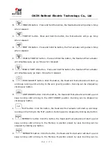
HEAD DN button

Press and hold the button, the Head actuator will go down. Stop 

when released. 

C. 

FOOT UP button

Press and hold the button, the Foot actuator will go up. Stop 

when released. 

D. 

FOOT DN button

Press and hold the button, the Foot actuator will go down. Stop 

when released. 

E. 

HEAD & FOOT UP button

Press and hold the button, the Head and Foot actuator 

will simultaneously go up. Stop when released. 

F. 

HEAD & FOOT DN button

Press and hold the button, the Head and Foot actuator 

will simultaneously go down. Stop when released. 

G. 

ZERO GRAVITY button: Click the button, the Head and Foot actuator will start up 

and keep running until arriving to the zero gravity position. Running can be stopped by 
clicking any button.   

H. 

ANTI SNORE button: Click the button, the Head and Foot actuator will start up and 

keep running until arriving to the ANTI SNORE position. Running can be stopped by 
clicking any button.   

I. 

FLAT button: Click the button, the Head and Foot actuator will start up and keep 

running until arriving to the FLAT position. Running can be stopped by clicking any button.   

J. 

MEMORY A button: Click the button, the Head and Foot actuator will start up and 

keep running until arriving to the Memory A position preset by user. Running can be 
stopped by clicking any button.   

K. 

MEMORY B button: Click the button, the Head and Foot actuator will start up and 

keep running until arriving to the Memory B position preset by user. Running can be 

Summary of Contents for ComfortBase

Page 1: ...c Technology Co Ltd Page 1 of 8 Operating Manual of Remote Control system 1 Interface of the remote control 2 Button description A HEAD UP button Press and hold the button the Head actuator will go up...

Page 2: ...or will start up and keep running until arriving to the zero gravity position Running can be stopped by clicking any button H ANTI SNORE button Click the button the Head and Foot actuator will start u...

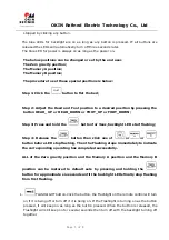
Page 3: ...and hold the button for 3sec backlight LED start flashing Step 4 Release the button then click one of or or button before LED stop flashing Then the Flashing stops immediately to indicate the corresp...

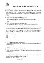
Page 4: ...el more strongly vibrating it is The strongest vibrating is level 3 and the weakest is level 1 Implement adjustment of the vibrating intensity is the way known as PWM Different duty cycle of PWM makes...

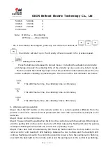
Page 5: ...vibrating time is 20minutes This LED flash a time the vibrating time is 30minutes 3 Wireless pairing operation Step1 Push the DIP Switch on the remote control to a certain position different from the...

Page 6: ...must be paired with the different remote control where the DIP Switch position is deferent Do not pair both control boxes with the same remote control or the different one but in which the DIP switch...

Page 7: ...e movement sequence is that the Foot actuator goes down until arrives to the limit the Head one goes down If release the button all movement will stop immediately including the massage motors It isn t...

Page 8: ...harmful interference to radio communications However there is no guarantee that interference will not occur in a particular installation If this equipment does cause harmful interference to radio or...

Reviews: