


43471801TH Rev.1
29 /
Oki Data CONFIDENTIAL
3.2
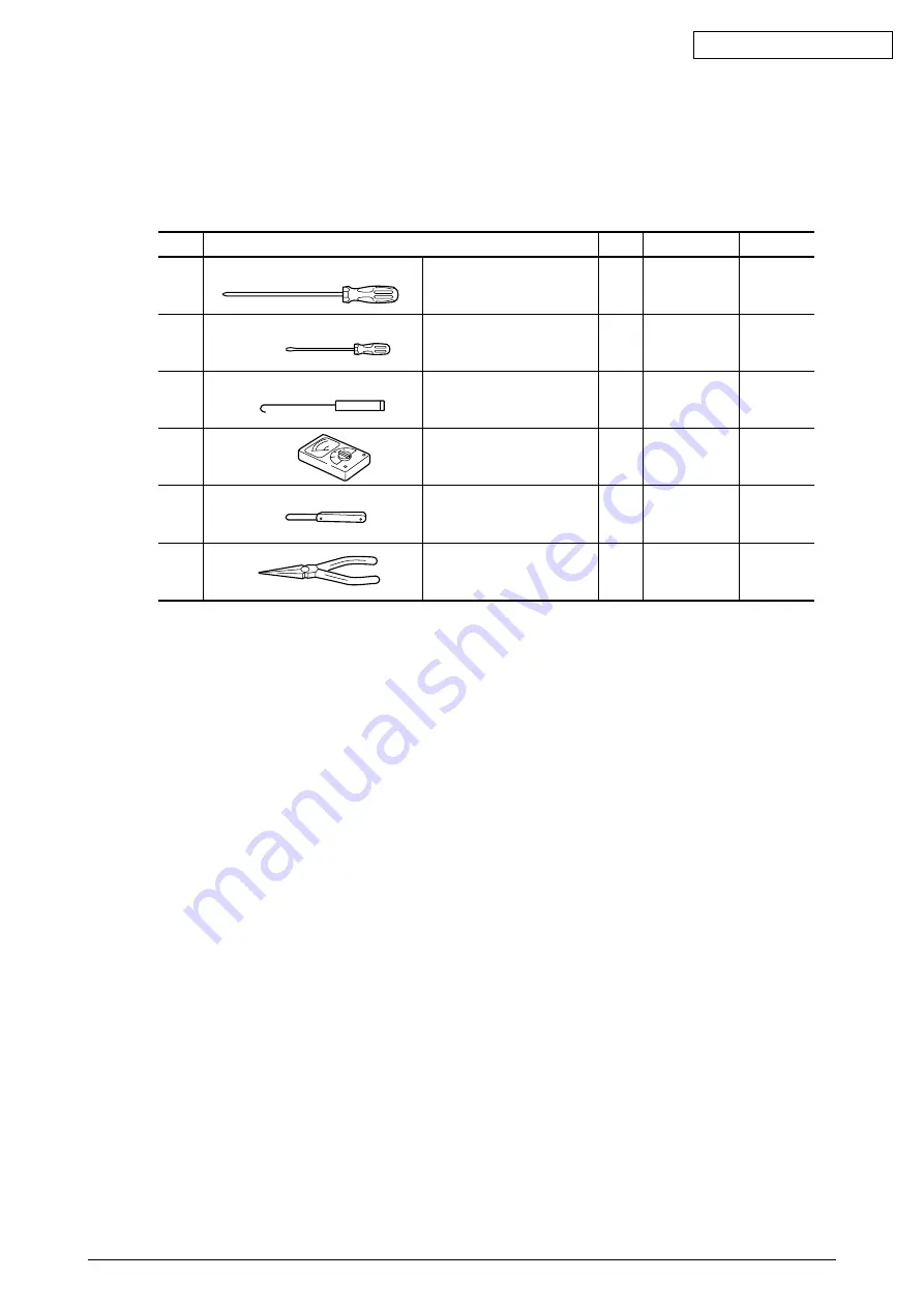
Service Tools
Table 3.1 lists the tools necessary for replacing printed circuit boards and parts of units in the
field.
Table 3.1 Service tools
1
No. 2-200 Phillips
1
Screws
screwdriver
3-5 mm
2
No. 3-100
1
screwdriver
3
Spring hook
1
4
Volt/ohmmeter
1
5
Feeler gauge
1
Head gap
adjustment
6
Pliers
1
No.
Service Tool
Q’ty
Use
Remarks


