


k)
Heavy oil direct start
l)
Restricted startup behavior
n)
Restricted safety loop
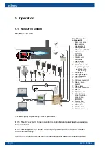
5.4 Burner operation and PI diagram, gas
Combustion air
Fan (50 - 280) ver. 1
The burner is equipped with a fan which is designed to produce consistently high
air pressure. This is required for flawless ignition and good combustion in modern
combustion chambers. A servomotor controls the air volume according to fuel
combustion.
Pre-purge and ignition
After the pre-purge, the servomotors run to ignition position, the ignition begins and
ignition gas valves open. Gas is released to the nozzle and ignited by an electric arc.
After the first safety time, both fuel valves open and the ignition flame ignites the main
flame.
Gas valve proving
Gas valve proving is carried out by a pressure switch that tests the double solenoid
valve and ignition gas valve tightness according to the burner control program phase.
The pressure switch carries out gas valve testing during controlled shutdown or during
the next pre-purge period.
Burner operation
During burner operation, the control unit adjusts servomotors according to capacity
controller inputs. Servomotors adjust the gas regulator valve and air dampers between
partial load and full load according to the capacity demand.
Burner shutdown
If the current partial load exceeds the capacity demand, the burner shuts down and the
double solenoid valve closes.
M4219 2305EN
83 (111)
Summary of Contents for GP-600 M
Page 2: ......
Page 16: ...Block diagram of contact links Block diagram ver 7 14 111 M4219 2305EN...
Page 87: ...5 5 Time sequence diagram gas use 7550f57e 0515 Gp1 ver 6 M4219 2305EN 85 111...
Page 113: ...M4219 2305EN 111 111...
Page 114: ...112 111 M4219 2305EN...
Page 115: ......


