p. 3
・
[OUTPUT] Terminal Specifications
[24V]: DC24V Output terminal
[OUT1]:
Output terminal for Request signal of Starting signal for screw feeding.
※
2 seconds after screw extraction, the output signal changes.
[OUT2]:
Output terminal signaling the set number of screws are to
be extracted.
※
For at least 2 sec., the output signal indicates Low output.
[OUT3]:
Output terminal signaling the set number of screws are to be extracted.
[OUT4]:
Output terminal for the 1st request of the starting signal after
the power is turned ON.
[OUT5]:
Output terminal signaling the screw feeding operation.
[OUT6]:
Output terminal for the 2nd or later request of the starting signal
after the power is turned ON.
[OUT7]:
Output terminal for the overload and stopped signal.
[OUT8]:
Output terminal for the extracting error and stopped signal.
[GND]:
Ground (0V Output) terminal for [24V]
・
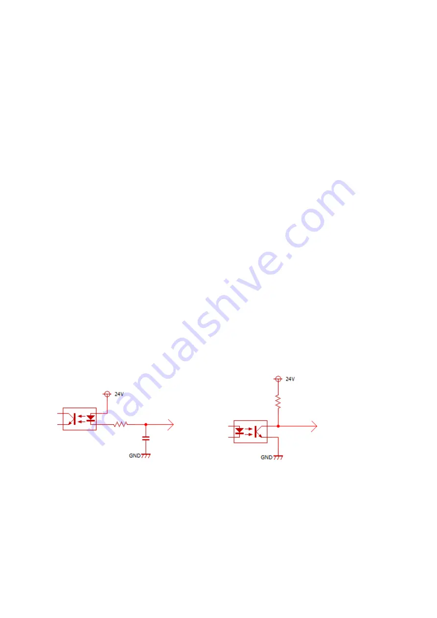
Internal circuits
The internal circuits for both the INPUT and OUTPUT terminals
are described below in Figures 3 and 4.
In FIG 3 & 4, 24V and GND are [24V] and [GND] terminals.
[24V] and [GND] on INPUT and OUTPUT use their respective terminals.
FIG 3. [IN*] terminal FIG 4. [OUT*] terminal
IN * terminal
OUT * terminal


