background image

CHAPTER 2  DIAGNOSTIC GUIDE 

2.1 TROUBLESHOOTING 

This section of the manual contains troubleshooting information.  Information is contained to 
isolate specific problems using Table 2-1, Diagnostic Guide  Follow all directions step by step.   
Make certain that the work area is clean.  Handle balance components with care.  Use 
appropriate Electro-Static Device. 

2.2 DIAGNOSTIC 

GUIDE 

Table 2-1 is a Diagnostic Guide designed to help locate the problem area quickly and easily.  
The probable causes are listed with the most common cause first.  If the first remedy does not 
fix the problem, proceed to the next remedy.  Before attempting to repair the balance, read all 
chapters of this manual to be familiar with the balance components and operation.  

2.2.1 Diagnosis 

1.  Isolate and identify the symptom 

2.  Refer to Table 2-1, Diagnostic Guide and locate the symptom.  

3.  Follow the suggested remedies in the order they appear. 

4.  Perform the indicated checks, or see the appropriate section of the manual. 

5.  Repair or replace the defective section of the balance. 

NOTE: 

If more than one symptom is observed, approach one area at a time, 
and remember that the symptoms may be interrelated. 

If a problem arises that is not covered in this manual, contact Ohaus Corporation for further 
information. 

Traveler™ Series Service Manual


2-1


Ohaus Corporation  www.ohaus.com


Summary of Contents for TA152

Page 1: ...SERVICE MANUAL Traveler Scales Ohaus Corporation 19A Chapin Road P O Box 2033 Pine Brook NJ 07058 2033 973 377 9000...

Page 2: ......

Page 3: ...time of publication but Ohaus Corporation assumes no liability arising from the use or misuse of this material Reproduction of this material is strictly prohibited Material in this manual is subject t...

Page 4: ......

Page 5: ......

Page 6: ...ale 3 1 3 3 Replacing the Load Cell 3 2 3 4 Replacing the Printed Circuit Board and Display 3 2 3 5 Replacing the Auxiliary Display s Printed Circuit Board 3 3 3 6 Setting Removing Legal For Trade Onl...

Page 7: ...NO TITLE 1 1 Power Connection 1 5 1 2 Battery Installation 1 5 1 3 Transportation Lock on Bottom Housing 1 5 1 4 Displays for Traveler Scout SE Carat Gold Series TAJ and TAG 1 6 1 5 Traveler Display I...

Page 8: ...mponents Appendix A Standard Calibration Explains procedures for Standard Calibration performed prior to using a scale and after service Appendix B Service Calibration Describes the Service Menu which...

Page 9: ...ons are not met TABLE 1 1 SPECIFICATIONS FOR TA MODELS Model TA152 TA301 TA302 TA501 TA1501 TA3001 TA5000 Capacity g 150 300 300 500 1500 3000 5000 Readability g 0 01 0 01 0 1 0 1 0 1 0 1 1 Linearity...

Page 10: ...s Counting Tare range To capacity by subtraction Stabilization Time 3 seconds Operating Temperature Range 50 104 F 10 40 C Operating Humidity Range 30 90 Pan Size mm 100 dia 137 x 140 1 TAJ2001 TAJ400...

Page 11: ...1 0 1 1 1 Off Center Load d Load Distance 1 1 1 1 1 1 1 1 1 Span Mass g 200 200 200 300 300 2000 2000 3000 3000 Linearity Masses g 100 200 200 300 200 400 300 600 300 600 2000 3000 2000 4000 3000 6000...

Page 12: ...off after no activity is detected for 4 minutes Figure 1 2 Battery installation Before operating the scale check that the Transportation Lock is in the unlock position Otherwise the scale will not be...

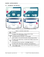
Page 13: ...Long Press Turn scale Off On Zero Off Yes Menu function Yes Used to accept the currently displayed setting Primary function Short Press Send the current display value to serial port if installed Print...

Page 14: ...All segments will appear briefly followed by a software revision number and then 0 00g Allow 20 minutes warm up time The scale should be calibrated before use See Appendix A 1 5 4 Power OFF To turn th...

Page 15: ...PC Off Off Hold Off Totalize Off Spec Gr Off C Off End Yes Print Stable Off APrint Off End Yes RS232 ON OFF on Baud 2400 Bits Parity 7 none Handshake none End Yes USB ON OFF on Baud 2400 Bits Parity 7...

Page 16: ...Figure 1 7 2 Connect the cable to an RS232 port on the computer printer or other device 3 Set the communications parameters to match on both devices 1 6 2 RS232 Commands All communication is accomplis...

Page 17: ...calibration L Initiate Linearity calibration 0M Gram mode 1M Ounce mode 2M Troy ounce mode 3M Pennyweight mode 4M Parts counting mode 5M Pound Mode 6M Newton 7M Kg 8M Lb oz 9M esc ddddaaaW Write word...

Page 18: ...problem proceed to the next remedy Before attempting to repair the balance read all chapters of this manual to be familiar with the balance components and operation 2 2 1 Diagnosis 1 Isolate and iden...

Page 19: ...on weight Slide the pin to the unlocked position Slide switch to the unlocked position Err 1 Invalid checksum data Cycle scale off on See Appendix C to restore data Replace PCB Err 2 Overload or under...

Page 20: ...ide of the scale using a damp cloth with warm water CAUTION DO NOT USE CHEMICAL CLEANERS OR SOLVENTS OF ANY TYPE SOME CLEANERS ARE ABRASIVE AND MAY AFFECT THE SCALE S FINISH 3 Check the Power Cord for...

Page 21: ...sition 7 When installing the new Load Cell insert the screws to secure the Load Cell to the Bottom Housing before reconnecting the wires to the PC Board While holding the Load Cell with your hand turn...

Page 22: ...ied by local weights and measures or approval agency by inserting a seal cable between the red hook on the Calibration Lock Tab and its white counterpart next to the locked position Follow these steps...

Page 23: ...CHAPTER 3 MAINTENANCE PROCEDURES Ohaus Corporation www ohaus com 3 4 Traveler Series Service Manual...

Page 24: ...dapter to the scale power receptacle located on the bottom of the scale or install four alkaline AA LR6 batteries 2 Plug the Power Cord into a suitable power source 4 3 Segment Display Test Turn the s...

Page 25: ...et Up Enter the menu and set the instrument to display the same units as the performance specifications Usually kg g or mg the default is g TEST PROCEDURE 1 Zero the instrument 2 Using a test mass app...

Page 26: ...________ 6 Calculate the Delta for each reading and record in the work sheet Delta Reading Mean 7 Calculate the Delta x Delta for each reading and record in worksheet 8 Add the ten Delta x Delta value...

Page 27: ...way between the center and the edge to the front of the Pan Note any differences in the displayed weight reading 4 Repeat the test for the back left and right position of the Pan 5 Maximum allowable c...

Page 28: ...ove the weight to point D and record the reading 7 If the reading at point A is negative file at points 1 and 4 AT AN ANGLE 8 If the reading at point B is negative file at points 1 and 2 STRAIGHT ACRO...

Page 29: ...000 1000 Load 1 200 300 1000 1000 1000 4000 Load 2 400 600 2000 2000 2500 4000 Load 3 500 1000 2500 3000 4000 5000 NOTE All masses are nominal values Be certain to use the same reference mass througho...

Page 30: ...ome shaped Draft Shield 3 Section 5 3 Traveler Scales with No Draft Shield NOTE In all cases where a part is replaced the balance must be thoroughly checked after the replacement is made The balance M...

Page 31: ...LISTS DIAGRAMS 5 1 TRAVELER SCALES WITH SQUARE DRAFT SHIELD HOUSING PARTS Figure 5 1 Traveler Scales with Square Draft Shield Housing Internal Parts Ohaus Corporation www ohaus com 5 2 Traveler Series...

Page 32: ...omplete 2a Pan 120mm 3a Pan Support 120mm 2a Pan Square 3a Pan Support Square 5 Function Label 6 Housing Top Bottom 7 Load Cell 8 Hardware Kit 9 PCB Main 10 Battery Cover with Weigh Below Hook 11 Inte...

Page 33: ...PARTS LISTS DIAGRAMS 5 2 TRAVELER SCALES WITH ROUND DRAFT SHIELD HOUSING PARTS Figure 5 2 Traveler Scales with Round Draft Shield Housing Parts Ohaus Corporation www ohaus com 5 4 Traveler Series Serv...

Page 34: ...HOUSING PARTS Drawing Item Description 1 Draft Shield Round 2 Pan 100mm 3 Pan Support 100mm 4 Level Bubble 5 Function Label 6 Housing Top Bottom 7 Load Cell 8 Hardware Kit 9 PCB Main 10 Cover Battery...

Page 35: ...5 PARTS LISTS DIAGRAMS 5 3 TRAVELER SCALES WITH NO DRAFT SHIELD HOUSING PARTS Figure 5 4 Traveler Scales with No Draft Shield Housing Parts Ohaus Corporation www ohaus com 5 6 Traveler Series Service...

Page 36: ...SHIELD HOUSING PARTS Drawing Item Description 2 Pan Square 3 Pan Support Square 4 Level Bubble 5 Function Label 6 Housing Top Bottom 7 Load Cell 8 Hardware Kit 9 PCB Main 10 Battery Cover w Weigh Bel...

Page 37: ...CHAPTER 5 PARTS LISTS DIAGRAMS Ohaus Corporation www ohaus com 5 8 Traveler Series Service Manual...

Page 38: ...ess as it will cause the process to fail 1 Press and hold the ENTER Cal button until CAL appears Cal 2 Press Yes CAL appears followed by a flashing C while a zero reading is stored C 3 The specified c...

Page 39: ...APPENDIX A STANDARD CALIBRATION Ohaus Corporation www ohaus com A 2 Traveler Series Service Manual...

Page 40: ...e Ramp value should be between 20 and 60 The actual value is not as important as how it changes It should increase as the weight on the scale is increased And the ramp display should remain constant w...

Page 41: ...e mid point value is acquired the display shows the second calibration point value 400 Pressing Yes after placing the prompted weight accepts the linearity full capacity weight The display shows C whi...

Page 42: ...An The display shows C while the scale acquires the zero value C The specified maximum mass weight flashes Place the indicated weight in the center of the Pan 200 Pressing Yes after placing the prompt...

Page 43: ...APPENDIX B THE SERVICE MENU Ohaus Corporation www ohaus com B 4 Traveler Series Service Manual...

Page 44: ...Hardware and Software Setup 1 First check that the scale s A Off feature under the SETUP menu is set to OFF If this setting is left ON the scale will shut off during configuration 2 Install the RS232...

Page 45: ...t match click the arrow next to the parameter and select the correct value See Figure C 2 7 Click the Test Command tab to test the communications See Figure C 3 Figure C 3 Config Tool s Test Command s...

Page 46: ...ox A and click OK D When the OK button highlights again click Update F Turn the scale off and then back on to save the data A B C D G Figure C 4 The Config Tool s Configuration Screen E F 3 If the Loa...

Page 47: ...APPENDIX C SOFTWARE SERVICE TOOL INSTRUCTIONS Ohaus Corporation www ohaus com C 4 Traveler Series Service Manual...

Page 48: ......

Page 49: ...80251719 P N 80251719 SERVICE MANUAL TRAVELER SERIES SCALES...

Reviews: