OGSI OG-15 Installation, Operation And Maintenance Manual Download Page 40

Effective 07/2014


36


Set-up & Installation


Although every 

OG-15/OG-20

unit is thoroughly tested and checked before it is 

shipped from our facility, the following steps are necessary to ensure that none of the 
internal components have been damaged during shipment.  This check should take less 
than five minutes to perform.  

(Refer to ‘

Initial Inspection’

 on page 2 and ‘

Unpacking 

Instructions

’ on page 5 before reading the instructions below)


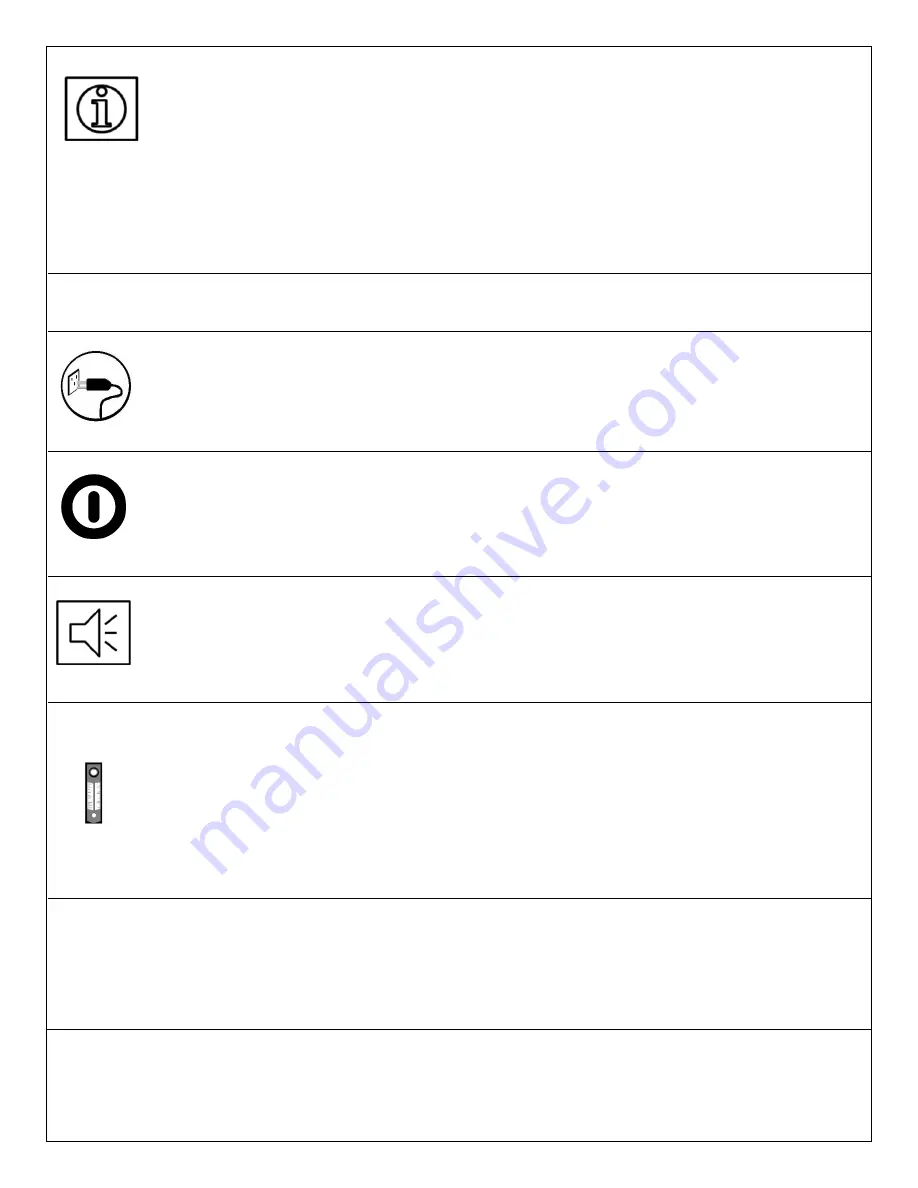
Make a visual inspection of the machine and make sure all parts are properly connected.   

(Refer to ‘

Components

’ section)


Connect the unit into a grounded electrical outlet.  A receptacle plug of local configuration 
will need to be attached first if the machine has been shipped outside North America.  


Push the 

ON/OFF

 green lighted power switch to the 

ON

 position and make sure that the 

green light is illuminated.  


Listen for the sound of the compressor to start operating.  If you do not hear it within a few 
seconds, shut the machine down immediately and call 

OGSI

 for assistance.  


Once the machine is operating, turn the knob on the upper part of the oxygen flow meter to 
adjust the oxygen flow to 

7 LPM

 (

0.4 Nm

3

/h)

 for 

OG-15

 and 

10 LPM (0.5 Nm

3

/h

) for 

OG-20

.  

The ball in the flow meter should be in the middle of the flow meter indicating 

7 LPM 

or


10 LPM

 flow for 

OG-15

 and 

OG-20

 respectively.  The oxygen pressure gauge should read 

12 

psi (0.83 bar)

 or 

20 psi (1.4 bar)

 for 

OG-15 

and 

OG-20 

respectively.  If it does not, turn the 

oxygen regulator either clockwise to increase the pressure or counter-clockwise to decrease it 
until it reaches 

12 psi (0.83 bar)

 or 

20 psi (1.4 bar)

 for 

OG-15 

and 

OG-20 

respectively.  


You should be able to feel oxygen being discharged from the lower left oxygen outlet port.   
If these things do not occur, check to make sure that none of the hose connections have 
come loose.  Call the 

OGSI Technical Service Department

 at 

(800) 414-6474

 (toll free 

number in USA and Canada) or 

(716) 564-5165

 if no loose connections are found and 

trouble persists.  


Summary of Contents for OG-15

Page 1: ...Maintenance Manual Oxygen Generating Systems Intl OGSI Division of Audubon Machinery Corporation 814 Wurlitzer Drive North Tonawanda New York 14120USA Tel 716 564 5165 Toll Free 800 414 6474 Fax 716 5...

Page 2: ...Page left intentionally blank...

Page 3: ...Components 10 Process Flow Description 26 Specifications 27 Performance Curve 31 Safety Precautions 33 Pre Installation 34 Required Operating Conditions 35 Set up and Installation 36 Operating Instru...

Page 4: ...2014 OGSI All rights reserved OGSI is a registered trademark This publication may not be reproduced in part or whole without written permission of OGSI...

Page 5: ...warranty policy features functions applications proper set up and installation operation and preventive maintenance of our products The following symbols are used throughout the manual Information Do...

Page 6: ...y you the consignee as OGSI shipping terms are Free On Board FOB North Tonawanda NY USA This means that once the equipment leaves our dock you are the owner of it OGSI has no legal claim to make again...

Page 7: ...ucts to OGSI Once the Products are repaired OGSI will ship the Products back to the original user and cover all costs incurred in shipping 2 OGSI shall repair or replace the Products excluding filter...

Page 8: ...roducts by anyone other than an authorized representative of OGSI The authorized service representative must obtain prior approval from OGSI s Service Manager before performing any warranty work c Ext...

Page 9: ...six 6 screws with nylon washers located on the front and both sides of the unit Lift the front cover up and away from chassis Remove packaging material from top behind and under the air compressor dr...

Page 10: ...oking should not be permitted in the area where the oxygen generator is located All oxygen connections and hoses should be kept clean and free of grease oil and other combustible materials Valves cont...

Page 11: ...end caps for years of reliable service Portable The OG 15 weighs 65 lb 29 kg without cover and the OG 20 weighs 67 lb 30 kg without cover These units are industrial strength oxygen generators Safe A...

Page 12: ...and OG 20 can be used in various applications A few examples are given below Hyperbaric Oxygen Therapy HBOT Fish Farming and Aquaculture Ornamental Glass Manufacturing Jewelry Manufacturing Bottled Wa...

Page 13: ...The process is described below Stage 1 Compressed air is fed into the first molecular sieve bed Nitrogen is trapped while oxygen is allowed to flow through Stage 2 When the sieve in the first bed bec...

Page 14: ...ive 07 2014 10 External Components Front View 1 Air Pressure Gauge 2 ON OFF Power Switch 3 Hours Meter 4 Anti vibration Feet Optional 5 Oxygen Pressure Gauge 6 Oxygen Flow Meter 7 Oxygen Pressure Regu...

Page 15: ...Effective 07 2014 11 Control Panel Magnified View 1 ON OFF Power Switch 2 Model Number 3 Oxygen Flow Meter Knob 4 Oxygen Pressure Regulator Knob...

Page 16: ...Effective 07 2014 12 Side Views Left 1 Vent Hole 8 minimum clearance 2 Cabinet 3 Reset Button 4 Voltage Label Right 1 Oxygen Outlet 2 Cabinet 3 Vent Hole 8 minimum clearance...

Page 17: ...e must be adjusted to this level when reading the flow meter The oxygen regulator can adjust the pressure Oxygen Pressure Regulator The regulator controls the oxygen delivery pressure level To adjust...

Page 18: ...l Components OG 15 Front View 1 Control Panel 2 Terminal Assembly Strip 3 Sieve Bed 4 Heat Exchanger 5 Air Compressor 6 Circuit Board 7 Pre filter 8 Valve Block 115 VAC or 230 VAC 9 Inlet Air Filter 1...

Page 19: ...e 07 2014 15 Back View Standard 1 Oxygen Receiver Tank 2 Cooling Fan 115 VAC or 230 VAC 3 Capacitor 4 Power Cord 5 Vent Holes 6 Purge Loop 7 Check Valves 8 Exhaust Muffler 9 Serial Number Locator Not...

Page 20: ...Effective 07 2014 16 Back View Quiet Muffler Option 1 Oxygen Receiver Tank 2 Female Elbow 3 Foam Filter 4 Exhaust Muffler 5 x Reducing Nipple...

Page 21: ...r less Front View 1 Terminal Assembly Strip 2 Sieve Bed 3 Regulator Adjustment Knob 4 Inlet Pressure Gauge 5 Filter Regulator 6 Inlet Check Valve 7 Compressed Air Inlet 8 Control Panel 9 Circuit Board...

Page 22: ...Effective 07 2014 18 Back View 1 Oxygen Receiver Tank 2 Cooling Fan 115 VAC or 230 VAC 3 Check Valves 4 Exhaust Muffler 5 Power Cord...

Page 23: ...nents OG 20 Front View 1 Control Panel 2 Terminal Assembly Strip 3 Sieve Bed 4 Heat Exchanger 5 Air Compressor 6 Circuit Board 7 Sieve Bed 8 Pre Filter 9 Valve Block 115 VAC or 230 VAC 10 Inlet Air Fi...

Page 24: ...ective 07 2014 20 Back View 1 Oxygen Receiver Tank 2 Cooling Fan 115 VAC or 230 VAC 3 Capacitor 4 Power Cord 5 Vent Holes 6 Purge Loop 7 Check Valves 8 Exhaust Muffler 9 Serial Number Locator Not Visi...

Page 25: ...ss Front View 1 Terminal Assembly Strip 2 Sieve Bed 3 Regulator Adjustment Knob 4 Inlet Pressure Gauge 5 Filter Regulator 6 Inlet Check Valve 7 Compressed Air Inlet 8 Control Panel 9 Circuit Board 10...

Page 26: ...Effective 07 2014 22 Back View 1 Oxygen Receiver Tank 2 Cooling Fan 115 VAC or 230 VAC 3 Check Valves 4 Exhaust Muffler 5 Power Cord...

Page 27: ...nd waste valves for each bed They direct feed air to each bed during oxygen production and waste nitrogen through the muffler to regenerate the sieve The cycle continues while the unit operates Inlet...

Page 28: ...IR COMPRESSOR 3 RELIEF VALVE 4 HEAT EXCHANGER 5 AIR PRESSURE GAUGE 6 LEFT VALVE 7 RIGHT VALVE 8 NOISE MUFFLER 9 LEFT PURGE ORIFICE 10 RIGHT PURGE ORIFICE 11 CHECK VALVE 12 OXYGEN RECEIVER TANK 13 PRES...

Page 29: ...ET AIR FILTER 2 N A 3 RELIEF VALVE 4 N A 5 AIR PRESSURE GAUGE 6 LEFT VALVE 7 RIGHT VALVE 8 NOISE MUFFLER 9 LEFT PURGE ORIFICE 10 RIGHT PURGE ORIFICE 11 CHECK VALVE 12 OXYGEN RECEIVER TANK 13 PRESSURE...

Page 30: ...er bed which continues the production process While the second bed is producing oxygen the first bed is releasing into the atmosphere the nitrogen it adsorbed under very low pressure through a waste g...

Page 31: ...minimum Response Time Approximately 2 minutes to attain maximum purity after initial start up or extended shut down Physical Oxygen Outlet Fitting B Size oxygen adapter Air Inlet Fitting OG 15 OG 15E...

Page 32: ...irement OG 15 Standard Domestic Optional International 115 VAC 60 Hz Single Phase 6 0 A 230 VAC 50 60 Hz Single Phase 3A OG 15E Compressor less Standard Domestic Optional International 115 VAC 60 Hz S...

Page 33: ...r Response Time Approximately 2 minutes to attain maximum purity after initial start up or extended shut down Physical Oxygen Outlet Fitting B Size oxygen adapter Air Inlet Fitting OG 20 OG 20E Compre...

Page 34: ...rement OG 20 Standard Domestic Optional International 115 VAC 60 Hz Single Phase 6 0 A 230 VAC 50 60 Hz Single Phase 3 0 A OG 20E Compressor less Standard Domestic Optional International 115 VAC 60 Hz...

Page 35: ...Effective 07 2014 31 Performance Curves Oxygen Purity vs Flow OXYGEN PURITY OXYGEN FLOW RATE SCFH OG 15 OXYGEN PURITY 3 OXYGEN PURITY OXYGEN FLOW RATE SCFH OG 15 E Compressor less OXYGEN PURITY 3...

Page 36: ...TE SCFH Standard Cubic Foot per Hour gas measured at 1 atmosphere and 70 F and 0 humidity OXYGEN PURITY OXYGEN FLOW RATE SCFH OG 20 OXYGEN PURITY 3 OXYGEN PURITY OXYGEN FLOW RATE SCFH OG 20 E Compress...

Page 37: ...oxygen generator within your facility In crucial applications it is important to have a backup supply of oxygen since the generator does not come with any reserve storage tank and requires electrical...

Page 38: ...that room should be well ventilated at least 5 air changes in the room per hour The oxygen generator will be discharging nitrogen into the atmosphere of the room and a nitrogen build up could be dange...

Page 39: ...ure The machine is designed for use over a temperature range of 40 F to 100 F 5 C to 38 C Since hot air has the ability to hold more water in the form of humidity than cool air operating the unit in h...

Page 40: ...perating If you do not hear it within a few seconds shut the machine down immediately and call OGSI for assistance Once the machine is operating turn the knob on the upper part of the oxygen flow mete...

Page 41: ...ecting it to an electrical outlet and pushing the switch on the machine to the ON position wait for 2 minutes for the unit to come up to maximum purity The oxygen delivery pressure should be set to 12...

Page 42: ...e and clean valves and spools completely Pressure Switch not functioning Machine not turning ON OFF at target pressures Faulty switch Remove switch and return for replacement Warning Signs Low Oxygen...

Page 43: ...py water Avoid the use of ammonia or other strong chemical based cleaning solvents This prevents dust and dirt from building up on the machine Air Compressor OG 15 OG 20 Only You should consider your...

Page 44: ...direct number By Telephone Outside the United States Your local International Access Code usually 0 or 00 followed by The Country Code for the U S which is 1 followed by our Area Code and Number 716 5...

Page 45: ...Effective 07 2014 Appendix...

Page 46: ...Page left intentionally blank...

Page 47: ...s Bottom Quad Seal Front Plugs Right Side Sieve Bed Elbows Top Elbow Compressor Top Quad Seal Plug Bottom Elbow Street Elbow Bottom Quad Seal Prestolok Elbow Product Tank Safety Valve Top Purge Loop O...

Page 48: ...Page left intentionally blank...

Page 49: ...essure Regulator 2150002 025 1 11 2 0 12 psi Dial Gauge Oxygen Pressure 2190001 LB1 1 11 2 0 60 psi Dial Gauge Air Pressure 2190001 LB2 1 Oxygen Flow Meter 2700001 002 1 Solenoid Valve Assembly 115 VA...

Page 50: ...001 1 Oxygen Pressure Regulator 2150002 025 1 11 2 0 60 psi Dial Gauge Air Pressure 2190001 LB2 1 11 2 0 30 psi Dial Gauge Oxygen Pressure 2190001 LB3 1 Oxygen Flow Meter 2700001 003 1 Solenoid Valve...

Page 51: ...ications to ensure consistency between AMC internal procedure and industry norms Safety Contamination such as grease dirt oil dust solvents weld slag sand rust paper fiber rags wood coal and previousl...

Page 52: ...d pick holding it under a wire brush grinding wheel or simply wiping it down with a clean rag Upon completion of pre cleaning the part should be clear of any visible contamination and ready for final...

Page 53: ...the introduction of contamination during the assembly process If immediate use is not intended or is impractical the O2 cleaned part will be packed in a manner to prevent recontamination Small to med...

Page 54: ...ervice Compressed Gas Association Inc 4221 Walney Road 5th Floor Chantilly VA 20151 www cganet com Oxygen Cleaning Procedure Rev L 8 05 RIX Industries Inc 4900 Industrial Way Benicia CA 94510 www rixi...

Page 55: ...5 4 4 3 OG 175 NR 25 18 12 5 11 10 8 6 5 5 4 OG 250 NR 30 22 5 15 13 11 9 7 5 7 6 5 OG 375 NR NR 30 27 22 5 18 15 13 11 8 7 OG 500 NR NR NR 30 27 22 5 18 15 13 11 8 OG 650 NR NR NR NR 30 27 22 5 18 15...

Page 56: ...quare Inch kW Kilowatt kWh Kilowatt hour ft3 Cubic Feet VAC Volts Alternating Current Hz Hertz SCFH Standard Cubic Foot per Hour SCFM Standard Cubic Foot per Minute LPM Liter Per Minute 1 bar 1 45 x 1...

Page 57: ...Effective 07 2014 X Maintenance Log Date Part Reason for Maintenance Authorized Service Technician Signature...

Reviews: