
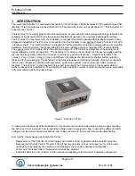


Echotrac CV100
User Manual
Page 18 of 18
Odom Hydrographic Systems, Inc.
May 28, 2008
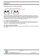
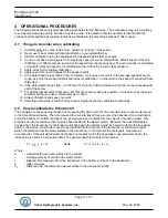
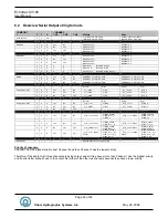
Transducer
d
r
d
a
d = ½ (a x t) – k + d
r
Many users may not be familiar with the parameter “Index” or “k”, although it is likely that they have seen the
results of combining transducer draft and index constant into one draft figure. If you have noticed that the
measured draft, or the distance from the face of the transducer to the water’s surface is not the same as the draft
value entered into the sounder, then you have seen the result of lumping both together. This phenomenon is
most evident when using dual frequency transducers where both high and low elements are in the same housing.
Often, the draft values are very different for the two frequencies if no adjustable “k” parameter is incorporated.
The difference in “k” or electronic delay between a 200 kHz element and a 24 kHz array is substantial, and is the
reason behind the difference between the two “Calculated Drafts”.
Once the “k” value is determined, it will not change until either the sounder or the transducer is changed.
The
Index parameter should be adjusted to make the measured draft and the calculated draft equal.
Since the accuracy of measuring the depth depends on the value used for the velocity of sound in water (along
with the other factors shown above), it is important that a realistic value for sound velocity is used. In water,
velocity is a function of temperature, salinity and pressure. Therefore, the sound velocity in one area may vary
from the sound velocity measured in another area. This means that whichever type of echo sounder is used, it
must be calibrated in order to provide the most accurate depth data at a given location.
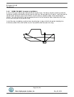
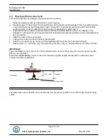
The most common calibration technique is the “Bar-Check” method. This method, when employed properly, has
the advantage of determining the sound velocity, draft, and index value. When this method of calibration is used,
acoustic sound waves are bounced off a suspended target that is lowered to a known depth between the
transducer and the bottom. In this situation it is desirable that the digitizer will see only the Bar (the target) and is
unable to lock on to acoustic returns from the bottom. Because the Echotrac CV employs a dynamic tracking gate
or window through which the digitizer looks for returns or echoes from the bottom, manual control for the position
and width of the gate is necessary. This will force the digitizer to only detect returns from the Bar. See section 4.3
on how to perform a bar-check.


