


Echotrac CV100
User Manual
Page 10 of 10
Odom Hydrographic Systems, Inc.
May 28, 2008
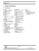
2.7 Serial
Ports
Serial 1
The Echotrac CV uses Serial port 1 to output depth data. Using a special Flash Utility program, the port is also
used to upgrade the software in the Echotrac CV. Another use of the port is to send commands to the Echotrac
CV or request certain parameter settings.
Serial 2
Serial port 2 is dedicated to connect the optional remote display to the Echotrac CV. The port can be configured
to use either an RS232 or RS422 protocol.
However, this feature is currently not supported with the Echotrac CV.
Serial 3
Serial port 3 is used to receive external GPS data in NMEA GLL or GGA format. It is best to only configure the
GPS to output only one of these strings as too much data can interfere with the communication processor’s other
tasks. When a GPS is connected to the Echotrac CV and is receiving position information, the Echotrac CV
100can output that GPS information on the Ethernet port.
Heave
Serial port 4 is used to receive motion sensor data in TSS1 format (heave). This port enables the Echotrac CV to
accept data from a motion compensator to apply corrections for the vertical movement caused by swells. The
Echotrac CV will only correct the depth for Heave. No corrections are done for Roll and Pitch.
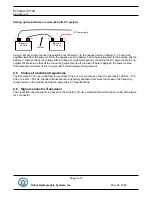
2.8 LAN
The LAN port is used by the Echotrac CV to send and receive data on the network. The Echotrac CV can be
connected directly to a Hub or a Switch using a regular UTP CAT-5 ethernet cable. A regular cable is also known
as a ‘straight’ UTP cable. When the Echotrac is connected directly to a computer, a so-called ‘cross-over’ UTP
cable must be used. When a computer is directly connected to the Echotrac CV using a crossover cable, the
operating system on the computer may take 2-3 minutes before the computer has accepted a valid IP address. To
prevent this delay, you can assign the computer a static IP address or use a Hub/Switch.
2.9 Power
button
The power switch in the ON position will power-up the internal circuitry. In the OFF position it will power-down the
internal circuitry.
2.9.1 Power-OFF
The main power switching circuitry is open in this position.
2.9.2 Power-ON
On "power-up", the unit performs a Self-test to check system memory and also tests the Non-volatile RAM battery
voltage. If there was a problem with the Non-volatile RAM, the factory defaults will be loaded. The unit then enters
the sounding mode and begins data acquisition.
2.9.3 STANDBY
The main power circuitry is energized, drawing current from the mains and providing regulated DC voltages to all
internal modules. The unit is no longer in the sounding mode when it is in the standby position. However, the
Parameter Entry System is enabled.
2.10 Power indicator
When the Echotrac CV is turned on, a red LED will be on to indicate that the internal systems have powered up
successfully. The red LED is located below the power button.


