04/26/02
9
Revision 1.11
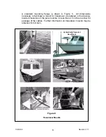
Figure 6 contains several examples of over-the-side mounts. For added
stability, it is recommended that lines connected to the flange be tied off
forward and aft.
The tilting aluminum deck plate design shown in Figure 6 is also shown
with the transducer fully deployed and in the stowed position. For added
support, it is advisable to secure the mounting pole at two points
whenever possible or tie a line or cable forward and aft from the flange.
ECHOSCAN transducers are normally delivered with 50 feet (or 15
meters) of cable. Proper routing of cables should be a priority
consideration when planning a new installation. Deck cable extenders of
variable lengths are available from Odom.
SPU Connections
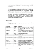
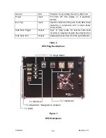
The Signal Processing Unit back panel connectors are described in Table
2. (Refer to Figure 7):
Designation
Direction
Description
RS232 Control
Input /
Output
Normally connected to the LCDU, this RS232
I/O port provides control input to the
ECHOSCAN SPU
RS232 Data
Output
Identical to “RS232 Control” but only an output
port only normally connected to the acquisition
computer
RS232
Output
RS232 Data Output (Auxiliary)
Auxiliary
(undefined) (for future use)
Side Scan Starboard
Output
Analog side scan video from the starboard
(right) side
Reference Transducer
Input /
Output
Connection to the built-in single beam
transducer (vertical)
Projector
Output
Drive signal for the 200 kHz projector array
Rx Array Inner
Input
Amplified signals from each of the 15 inner
beam receivers plus the port side scan receiver
Rx Array Outer
Input
Amplified signals from each of the 15 outer
beam receivers plus the starboard side scan
receiver
Summary of Contents for ECHOSCAN
Page 19: ...04 26 02 19 Revision 1 11 Blanking aeration Figure 17 Blanking Feature...
Page 38: ...04 26 02 38 Revision 1 11 EXTENDER CABLE WIRING...
Page 39: ...04 26 02 39 Revision 1 11 TRANSDUCER CABLES...
Page 40: ...04 26 02 40 Revision 1 11...
Page 41: ...04 26 02 41 Revision 1 11...
Page 42: ...04 26 02 42 Revision 1 11 JUNCTION BOX WIRING...
Page 43: ...04 26 02 43 Revision 1 11...
Page 44: ...04 26 02 44 Revision 1 11 HEADING SENSOR WIRING...


