


04/26/02
32
Revision 1.11
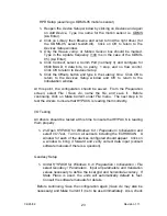
Figure 18
ECHOSCAN CALIBRATION
(Bi-Level Bar Check Method)
draft
Level 1
Level 2
DEPTH =
2
+ k + DRAFT
V x (pulse travel time)
s
As seen from the above equation, depth measurement
accuracy is primarily dependent upon the accuracy of two
external variables; Vs (sound velocity in water) and
DRAFT (the distance between the transducer and the
water surface). The bi-level bar check procedure
described below offers the most straightforward approach
to multibeam calibration in that both DRAFT and Vs
corrections are optimized. The calibration may be very
accurate, current and wind conditions permitting. Even
the system constant (k) is automatically compensated
using this method.
1. Lower the bar to a depth of 4 meters (or 10 feet) below the transducer. This will
be Level 1.
2. Pull down the
Digitizer Settings
menu on the LCDU, select
Range Gate
, and
adjust the
GATEDEPTH
to Level 1 depth. Set the
GATEWIDTH
to 2 meters.
Allow time for the digitizer to "lock in".
3. Pull down the
Setup
menu and adjust
Draft
as required to correct the depth value
displayed below
Channel #
. Normally, Channel 15 is monitored.
4. Lower the bar to Level 2 and set
GATEDEPTH
to Level 2 (depth limited only by
chain length, water depth, or current and wind conditions).
5. Under
Setup
, adjust the
Velocity
correction until the depth value displayed is
correct.
6. Return the bar and
GATEDEPTH
setting to Level 1 and repeat the
Draft
adjustment (step 3).
Summary of Contents for ECHOSCAN
Page 19: ...04 26 02 19 Revision 1 11 Blanking aeration Figure 17 Blanking Feature...
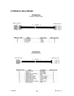
Page 38: ...04 26 02 38 Revision 1 11 EXTENDER CABLE WIRING...
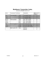
Page 39: ...04 26 02 39 Revision 1 11 TRANSDUCER CABLES...
Page 40: ...04 26 02 40 Revision 1 11...
Page 41: ...04 26 02 41 Revision 1 11...
Page 42: ...04 26 02 42 Revision 1 11 JUNCTION BOX WIRING...
Page 43: ...04 26 02 43 Revision 1 11...
Page 44: ...04 26 02 44 Revision 1 11 HEADING SENSOR WIRING...


