background image

10  How the C-Quant works

30 / 56

Instruction Manual C-Quant ( G/80000/1007/en)

.

During the examination a number of short stimuli are presented to the patient and he is
then asked to decide which of the two test fields flickers more intensely. 

The following example illustrates the underlying idea. 

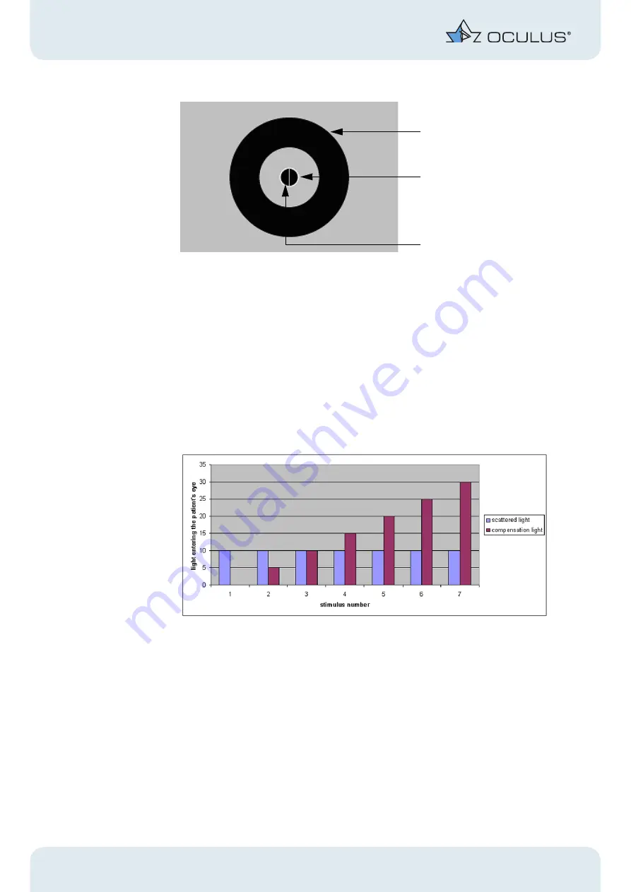
The left test field is off all the time. 

In the right test field compensation light appears counter-phase to the straylight source
at varying intensity. 

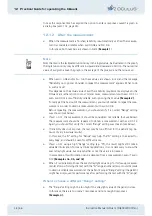
We will assume that patient has a straylight value of 10. The dimensional unit of stray-
light is disregarded in this example because it has no significance for understanding the
measurement principle.

Seven stimuli for the compensated field are shown:

Fig. 10-2: Seven stimuli

The left test field corresponds to stimulus numbher 3 all the time.

If the patient states that the left test field flickers more intensely, this is counted as "0".
If he sees the right test field flicker more intensely, this gives "1". 

„

For the individual stimuli this has the following consequences: 

1

Here no compensation light is presented, so that the two test fields appear the same.
Given sufficient test repetition the patient will choose right just as often as left, giv-
ing an average value of 0.5.

straylight source (outer ring)

right test field

left test field

Summary of Contents for C-QUANT

Page 1: ...OCULUS C QUANT INSTRUCTION MANUAL...

Page 2: ...ed in cooperation with Dr Tom van den Berg PhD from the Netherland Ophthalmic Research Institute of the Royal Academy NORI in 2005 merged into the netherlands institute for Neuroscience www nin nl in...

Page 3: ...a Management 7 8 1 Starting Patient Data Management 7 8 2 Entering new patients 7 8 3 Selecting existing patients 8 8 4 Deleting examinations 9 8 5 Patient data 9 8 6 Exporting patient data 10 8 7 Imp...

Page 4: ...r operating the C Quant 35 12 1 Measuring procedure 35 12 1 1 Patient instruction 36 12 1 2 After the measurement 38 12 2 Measurement Examples 40 13 Troubleshooting 49 14 Inserting corrective lenses 4...

Page 5: ...t This chapter contains a summary of the most important points regarding these safety matters Attention Do not use the device if you have not understood the instruction manual Make sure to keep this i...

Page 6: ...rvice department 2 2 Pictogram definitions Attention Identifies a potentially dangerous situation which may cause minor injury or damage to property Note Instructions for use and useful or important i...

Page 7: ...rate the C Quant in rooms used for medical purposes if VDE 0100 installa tion procedures have been observed Do not force any plug connections If you are unable to make a plug connection check whether...

Page 8: ...are to observe the safety precautions given above 4 Transportation and Disposal 4 1 Transport and storage instructions Great care must be taken when transporting the C Quant from one location to anoth...

Page 9: ...be no light scattering at all but because the eye media are not optically ideal there will always be some light scattering which degrades the image projected on the retina thus the quality of vision...

Page 10: ...nt with the PC via the serial or the USB cable Connect the low voltage socket of the supplied desktop power supply to DC input connector Connect the AC power cable to the desktop power supply Connect...

Page 11: ...en displays the user interface for Patient Data Management In case the user interface does not start automatically Click the C Quant icon on the desktop Fig 8 1 Patient Data Management Note To enter t...

Page 12: ...alphabetical order Click Search to quickly find the patient you require from the list Enter the patient s name or the first letter of the name in the Last name field Optionally you can search for the...

Page 13: ...e to delete individual examinations from the patient data Click Delete exam underneath the list of examinations You will be asked if you really want to delete the examination Fig 8 4 Delete individual...

Page 14: ...asurement data to another storage medium e g USB drive Sending stored data by e mail In Patient Data Management select the patient you require You can select a patient s entire data master or individu...

Page 15: ...e program is updated on the C Quant PC sender the program on the other PC recipient must also be updated 8 7 Importing patient data Import the patient and examination data you have received into your...

Page 16: ...F for a network drive Saving data can be done in a number of ways Save all data If this option is selected all examination and patient data are saved Changed and new data only If this option is selec...

Page 17: ...f the source from which the data are to be restored Click on the button to select the drive and directory from which the data are to be restored Click the Restore button for uploading the data from th...

Page 18: ...ngs are made here Fig 8 8 Main Setting Language Specify the language which the program should use Optional items for patient Optional information can be entered here Such information can then be activ...

Page 19: ...can be set up for different configurations The settings in the following fields can then be set separately for each configuration The user is then selected from the drop down menu and is activated by...

Page 20: ...nt data is always created locally on your PC and is used as a transfer folder for transfer of the data to the database Here again the name is always the name of the device followed by the extension DA...

Page 21: ...Alternatively the drive and the directory from which the data are to be imported or exported can be searched for by pressing the button Folder in field Import Export This field is for entering the let...

Page 22: ...nsfer takes place via the standard E mail function of your computer SMPT If an E Mail program is not installed on your PC activate the option SMTP The data transfer then takes place directly based on...

Page 23: ...80000 1007 en 19 56 8 9 5 Settings Interface Fig 8 12 Interface Box On this tab panel you can specify the storage locations for various interface types These interfaces are intended for the integrati...

Page 24: ...d reader you can read your patient data directly from the patient s insurance card into the OCULUS Patient Data Management Click on the Enable checkbox To install and configure your smart card reader...

Page 25: ...your network does not meet the system requirements to run Version 6 x then the use of both versions in the network is unavoidable In that case just one PC with Version 6 x must be configured such tha...

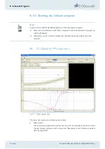
Page 26: ...start the Examination program by clicking C Quant Alternately you can start the program by double clicking the patient you have selected 9 C Quant Program Fig 9 1 C Quant program menu The menu bar con...

Page 27: ...left corner of the main window Fig 9 2 Common data 9 1 2 Examination specific data Fig 9 3 Relevant data to the examination This is where to enter all data relevant to the examination Eye Select the...

Page 28: ...the patient responds otherwise the program issues a warning The third test stimulus is difficulty for many patients Click Continue anyway if the patient shows proper understanding Fig 9 5 Warning mis...

Page 29: ...hows the examination date the patient s age at the time of exam ination the examination duration and the quality parameters Esd and Q Esd is the expected standard deviation of the individual measureme...

Page 30: ...the gray area gives the range of normal variation If the red dot is outside the gray area this signifies a conspicuous finding 9 1 4 Examination fields Stimulus field view Fig 9 8 Stimulus field This...

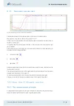
Page 31: ...gram are represented by different symbols depending on the phase currently being examined instruction phase dark phase light phase Extensive studies have shown that the results follow a specific curve...

Page 32: ...e is projected onto the retina However some of the light is scattered by the lens and other parts of the eye and is thus projected on the part of the retina onto which the test field projects fovea On...

Page 33: ...se Now the brightness of the test field is adjusted until the patient no longer sees any flicker This yields his or her straylight value 10 2 Compensation comparison method Determining the exact stray...

Page 34: ...is disregarded in this example because it has no significance for understanding the measurement principle Seven stimuli for the compensated field are shown Fig 10 2 Seven stimuli The left test field c...
Page 35: ...as intense as the scattered light meaning that the flicker intensity is 20 10 10 equal to that in the other test field The patient will therefore find that the two test fields flicker with equal inten...

Page 36: ...onfusing differences in flicker intensity with differenc es in brightness the instrument continually adjusts the test fields so that they have equal average brightness at each presentation The absciss...

Page 37: ...esult of the dark phase gives a reasonably good approximation of the patient s stray light value To determine it with greater precision he is now shown 13 stimuli in the light phase which are grouped...

Page 38: ...usly adjusted When the examination has been completed the result fields show the final values If during the examination the patient fails to respond to a stimulus within two seconds the following warn...

Page 39: ...his chapter gives some examples of possible measurement outcomes which can be use ful to interpret your own results especially when measurement reliability is not optimal It is assumed that you are al...

Page 40: ...y cases if straylight increase is mild If high straylight values are expected e g with cataract or corneal turbidities settings F medium log s or G high log s must be used G can also be used if you wa...

Page 41: ...nd also here you must make a choice following your first impulse Optional information only if the patients ask one measurement consists of about 25 presentations and usually takes 1 5 to 2 minutes Mak...

Page 42: ...0 08 Before repeating the measurement you should verify if a correct Range setting was chosen see below If esd 0 12 the measurement should be considered not reliable but see below The measurement sho...

Page 43: ...ting the measurement with the same Range setting will not yield a lower esd value You can only improve reliability by choosing a different Range setting Note It is not always clear if the chosen range...

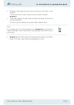
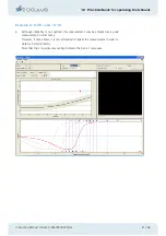
Page 44: ...40 56 Instruction Manual C Quant G 80000 1007 en 12 2 Measurement Examples Example 1 esd 08 and Q 1 This is a reliable measurement Note that there is almost no overlap between the 0 and 1 responses Mo...

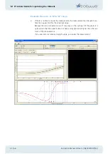
Page 45: ...le 2 0 08 esd 0 12 Although reliability is not optimal this measurement may be accepted as a good measurement in most cases However if time allows it is recommended to repeat the measurement in order...

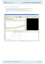
Page 46: ...easurement this measurement can be used to es timate an upper limit for the straylight value Because there is a consistent row of 1 responses in the right part of the graph it is quite certain that th...

Page 47: ...e of this measurement can be used to estimate an upper limit for the straylight value If you decide to repeat the measurement the surplus of 1 responses would suggest choosing a lower Range setting as...

Page 48: ...xamples 3a and 3b only esd is so high that no estimation for the straylight value could be calculated log s 6 00 is a meaningless value However you can make this estimation yourself by looking at the...

Page 49: ...00 1007 en 45 56 Example 4 Range setting too high This measurement went very well only there are too many 1 responses and not enough 0 responses for a reliable estimation of the straylight value Relia...

Page 50: ...t G 80000 1007 en Example 5 Range setting too low There are too many 0 and not enough 1 responses for a reliable estimation of the straylight value The measurement reliability can be improved by repea...

Page 51: ...Example 6 unreliable measurement at low Range setting From this result you can not tell if the Range setting was chosen too low or if the test is too difficult for the patient In both cases it is wise...

Page 52: ...uction Manual C Quant G 80000 1007 en Example 7 reliable measurement at high Range setting The same patient as in Example 6 but measured with the G setting This is a reliable measurement esd 0 08 and...

Page 53: ...No function after the mains switch is turned on the mains switch does not light up C Quant is not connected to the mains supply There has been a power failure or the power outlet is not active Plug t...

Page 54: ...n use Cleaning enameled surfaces Take care not to let cleansers enter the instrument We generally recommend using an antistatic cleanser for plastic surfaces to inhibit recontamination Otherwise you c...

Page 55: ...oft cloth 16 Terms of Warranty and Servicing 16 1 Terms of warranty The C Quant you have purchased is a high quality OCULUS product This C Quant was carefully manufactured using quality materials and...

Page 56: ...ly extensions adjustments changes or repairs are carried out by unauthorised personnel if the C Quant is maintained improp erly or if it is handled incorrectly If the work described above is carried o...

Page 57: ...ion of Conformity We declare in our responsibility that this product complies with the following norms or normative documents EN 60601 1 EN 60601 1 2 as stipulated by Guideline No 93 42 EEC for medica...

Page 58: ...g Dimensions W x D x H 250 x 325 x 380 mm Interface RS 232 V 24 sub D USB 1 1 Typ B Type of protection against electrical shock Protection class 1 Level of protection against electrical shock Type B L...

Page 59: ...L van Rijn LJ van den Berg TJTP Reliability of the compensa tion comparison stray light measurement method J Biomed Opt 11 34027 2006 Van den Berg TJTP van Rijn LJ Michael R Heine C Coeckelbergh T Ni...

Page 60: ...19 Bibliography 56 56 Instruction Manual C Quant G 80000 1007 en...

Page 61: ...The following pages remain free and offer space for personal notes...

Reviews: