background image

11

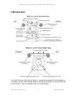
Tilt Lock Pin 

The tilt lock pin on the left side of the head is used to lock the head in a 
horizontal position. The lock pin is actuated by a flip lever with red (locked) and 
green (unlocked) label indicators.

Illuminated Bubble Level 

The bubble level on the left side of the head can be illuminated by pressing the 
display actuator button. The light will go out after approximately 15 seconds.

Handle Mounting 

Handle mounting points are located at the front and rear of the head, on both the 
left and right sides. A telescoping extension handle is supplied and is attached 
using the handle clamp, with angular adjustment available on the rosette 
serrations. Additional handles, including a front handle and accessories can also 
be installed.

Camera Mounting Platform 

The camera is attached to the head by means of: an OConnor geared plate; an 
OConnor plate; a 120mm Euro plate; a Panavision dovetail plate; or an Arriflex 
dovetail plate. The platform will accept geared or non-geared plates.

Mitchell Mount 

The 120EX head is provided with a standard Mitchell base mount. 

Operator's Guide - OConnor 120EX Pan and Tilt Head 

www.ocon.com 

OConnor Engineering

Summary of Contents for 120EX

Page 1: ...is document may be stored in a retrieval system transmitted copied or reproduced in any way including but not limited to photocopy photograph magnetic or other record without the prior agreement and permission in writing of Vitec Group plc OConnor is a registered trademark of Vitec Group plc 120EX Pan Tilt Fluid Head Operator s Guide Part No C1225 4980 ...

Page 2: ...logy OConnor can offer the features it has become famous for with the additional benefit of extended capacity With a new counterbalance mechanism at the heart of the EX technology the 120EX can be boosted into EX mode to achieve a whole new realm of counterbalance True and accurate balance is achieved through the sinusoidal EX counterbalance technology The EX drag technology is ultra smooth and st...

Page 3: ...camera payloads forward and backwards on the head with this mechanism Geared and non geared plates can be used on the platform OConnor s fluid drag system allows an extremely quick pan movement from one position to another recovering instantly without any spring back You can set up easily in low light conditions using the illuminated level bubble and back lit display Once again thank you for choos...

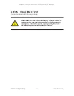
Page 4: ...is a risk of personal injury injury to others or damage to the pan and tilt head or associated equipment appropriate comments appear highlighted by the word WARNING and this warning triangle symbol Operator s Guide OConnor 120EX Pan and Tilt Head www ocon com OConnor Engineering ...
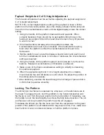
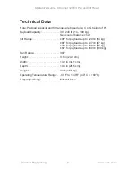
Page 5: ...0 lb 54 kg 80 for payloads up to 147 lb 67 kg 70 for payloads up to 188 lb 85 kg 60 for payloads up to 240 lb 109 kg Pan Range 360 Height 9 8 in 24 8 cm Width 13 2 in 34 1 cm Depth 10 4 in 26 5 cm Weight 34 lb 15 5 kg Operating Temperature Range 40 F to 140 F 40 C to 60 C Dolly tripod fixing Mitchell base Operator s Guide OConnor 120EX Pan and Tilt Head www ocon com OConnor Engineering ...
Page 6: ...R ENGINEERING 100 Kalmus Drive Costa Mesa CA 92626 Tel 714 979 3993 Fax 714 957 8138 Camera Dynamics Inc OCONNOR ENGINEERING 2701 N Ontario St Burbank CA 91504 Tel 818 847 8666 Fax 818 847 1205 E mail info ocon com Or visit our website www ocon com and use the contact form Operator s Guide OConnor 120EX Pan and Tilt Head www ocon com OConnor Engineering ...
Page 7: ...ck Pin 11 Illuminated Bubble Level 11 Handle Mounting 11 Camera Mounting Platform 11 Mitchell Mount 11 Operation 12 Installing The Head 12 Handles 12 Eyepiece Leveler 12 Mounting A Camera 13 Stability 13 Balancing The Head 14 Fore And Aft Balance 14 Payload Weight And C of G Height Adjustment 16 Locking The Platform 16 Pan And Tilt Locks 17 Pan And Tilt Fluid Drag 17 The Balance Display 17 Low Bat...

Page 8: ...Replacement 19 Balance Mechanism Calibration 20 Adjusting The Lock Levers 20 O Connor Contact Information 21 Headquarters 21 USA 21 China 21 France 21 Germany 21 Japan 21 Singapore 21 UK 21 Operator s Guide OConnor 120EX Pan and Tilt Head www ocon com OConnor Engineering ...
Page 9: ...unique and patented EX counterbalance mechanism for true and accurate balance EX drag assemblies for ultra smooth pan and tilt motions and an adjustable camera mounting plate Operator s Guide OConnor 120EX Pan and Tilt Head www ocon com OConnor Engineering ...
Page 10: ... the setting of the balance mechanism on a scale of 0 182 Press the display actuator button to illuminate the display and adjust the counterbalance crank At settings above 100 the EX indicator will turn on to alert you to the reduced tilt range The display turns off automatically approximately 15 seconds after you stop adjusting The display dims in dark surroundings Ultra Smooth Fluid Drag Both th...

Page 11: ...the head on both the left and right sides A telescoping extension handle is supplied and is attached using the handle clamp with angular adjustment available on the rosette serrations Additional handles including a front handle and accessories can also be installed Camera Mounting Platform The camera is attached to the head by means of an OConnor geared plate an OConnor plate a 120mm Euro plate a ...

Page 12: ...the handles on the rosette handle mounts and adjust the position before tightening the clamps Adjust the length of the telescoping handle as desired Eyepiece Leveler If required install the optional undermount eyepiece leveler EPL assembly on the left hand side below the counterbalance crank The eyepiece leveler is compatible with Arri s eyepiece rods Alternatively the rear mount eyepiece leveler ...

Page 13: ...ess down and hold the platform hook release red tang on the left hand side of the head 5 Position the camera and mounting plate on top of the head and release the hook to secure the mounting plate 6 Engage the platform release lever by rotating it towards the platform 7 Install the remainder of the payload lens zoom and focus controls viewfinder prompter etc Stability WARNING When mounting the hea...

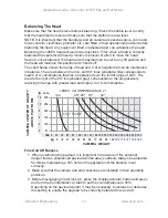
Page 14: ...ll maintain this position with hands off The chart below shows the range of load and C of G heights that can be maintained in balance The area between the min and 90 lines shaded white corresponds to load C of G combinations that can be balanced over the full tilt range of 90 The area to the right of the 90 line shaded grey corresponds to the progressively reducing tilt range with greater load and...

Page 15: ... needed to disengage b Other Mounting Plates With the help of an assistant carefully slide the camera payload and plate forwards or backwards until the payload is balanced fore and aft 10 The horizontal balance is correct when no perceptible tilting force can be felt on the handle with the platform level and with the tilt lock pin disengaged 11 Fully engage the platform release lever to secure the...

Page 16: ...ilt the platform upward and downward to recheck the balance Readjust counterbalance until balance is achieved 5 Make a note of the final counterbalance setting to simplify re balancing this particular payload 6 When the payload weight and C of G height adjustment is complete check that the fore and aft balance is still correct Re adjust the position of the sliding plate if necessary 7 After balanc...

Page 17: ...oth movement Control knobs on the right side of the head are used to adjust the drag settings over the range of 0 to 9 The pan drag knob is the smaller one at the base of the head The larger tilt drag knob is in the center on the tilt drag housing To increase drag turn the knob clockwise towards a higher setting To decrease drag turn the knob counter clockwise towards a lower setting The Balance D...

Page 18: ...ssary see below No other routine maintenance is required Cleaning During normal operation the only cleaning required is a periodic wipe down with a lint free cloth Any dirt that accumulates during storage or periods of non use may be removed with a semi stiff brush Particular attention should be paid to the dovetail faces of the camera mounting area NOTE Use only detergent based cleaners DO NOT us...

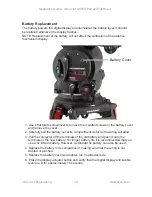
Page 19: ... will allow 3 Pull the connector off the terminals of the old battery and push it onto the terminals of the new battery For longer battery life it is recommended that you use a 9v lithium battery However a standard 9v battery can also be used 4 Replace the battery in its compartment making sure that the wiring is not twisted or pinched 5 Replace the battery cover and tighten the 3 slotted screws 6...

Page 20: ...ory and the display turns Off 6 Err is displayed for 2 seconds if the calibration fails A failure will occur if insufficient balance stroke was measured and set Ensure that the end of travel is used when setting maximum and minimum balance points 7 Calibration mode will time out after 1 minute to save battery life The system will revert to the previously stored values 8 After calibration re balanc...

Page 21: ...6199 Tel 65 6297 5776 Fax 65 6297 5778 UK Western Way Bury St Edmunds Suffolk IP33 3TB UK Tel 44 1284 752121 Fax 44 1284 750560 Sales Fax 44 1284 757929 Headquarters 100 Kalmus Drive Costa Mesa CA 92626 USA Tel 714 979 3993 Fax 714 957 8138 USA 709 Executive Blvd Valley Cottage NY 10989 USA Tel 1 845 268 0100 Fax 1 845 268 0113 2701 N Ontario St Burbank CA 91504 USA Tel 1 818 847 8666 Fax 1 818 84...

Reviews: