background image

 6 

Ocean Matrix 

www.oceanmatrix.com 


Ocean Matrix OMX-10HMIP0002 & OMX-11IPHM0002


Installation


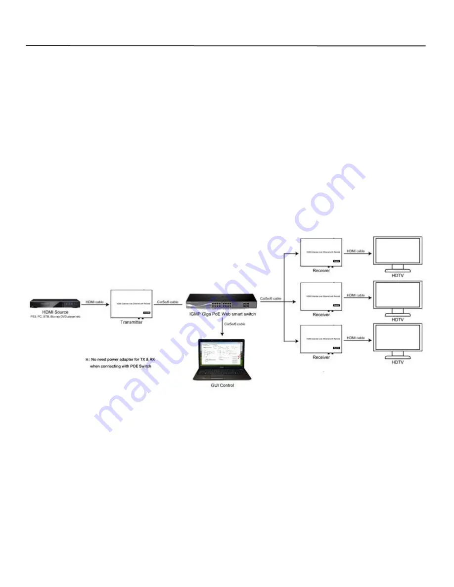
POINT-TO-MANY CONNECTION—Refer to instructions on the included CD 

1.  Set the IP addresses for the transmitter and the receiver and prepare the switch as instructed previously. 
2.  Connect the source device and the TX using HDMI cable. 
3.  Connect the HDMI looping output of the TX to the local HDMI display. 
4.  Connect the TXs and the switch/router using CAT5e/6 cable. 
5.  Connect the HDMI displays and the HDMI RXs using HDMI cable. 
6.  Connect the IR TX cable to the IR TX port on the transmitter. 
7.  Connect the IR RX cable to the IR RX port on the receiver to control the source at the RX end. 
8.  Connect one RS232 cable from the PC or system to the RS232 port on the TX. 
9.  Connect one RS232 cable from the RX to the RS232 device to be controlled. 
10. Turn the TX and the RX on using the included power supplies. 
11. Notes 



Daisy chain the switch if more RJ45 ports are needed 



You can add up to 255 receivers 

MANY-TO-MANY CONNECTION—Refer to instructions on the included CD 

1.  Set the IP addresses for the transmitter and the receiver and prepare the switch as instructed previously. 
2.  Connect the source device and the TX using HDMI cable. 
3.  Connect the HDMI looping output of the TX to the local HDMI display. 
4.  Connect the TXs and the switch/router using CAT5e/6 cable. 
5.  Connect the RXs and the switch/router using CAT5e/6 cable 
6.  Connect the HDMI displays and the HDMI RXs using HDMI cable. 
7.  Connect the IR TX cable to the IR TX port on the transmitter. 
8.  Connect the IR RX cable to the IR RX port on the receiver to control the source at the RX end. 
Continued 

Point to Many Configuration Example


Summary of Contents for OMX-10HMIP0002

Page 1: ...ne Transmitter One 5VDC 1A Power Adapter One IR Transmitter Cable One IR Blaster Extension Cable Remote Control Two Mounting Brackets Screws One Phoenix Plug Set Up and Installation CD Receiver Kit In...

Page 2: ...ta Status Red Power On 9 HDMI Output 10 CAT5e 6 I O 11 IR RX 1 RS232 Port 2 IR Ext 3 Channel Group ID 4 Channel Down 5 Channel Up 6 Reset Button 7 Power Input 8 LED Indicators Green Data Status Red Po...

Page 3: ...P so that the switch assigns a unique IP for the transmitter and receiver Don t change the IP for the units manually 2 Set the IP Via Web Browser When using a switch that doesn t support DHCP change t...

Page 4: ...an example if the connection is The group ID of the transmitters is TX1 01 TX2 02 TX3 03 If you need to display Source on TV1 then set the Group ID of RX1 the same as TX1 7 Setting the Group ID and Ba...

Page 5: ...F 2 Connect the source and the TX using HDMI cable 3 Connect the HDMI looping output of the TX to the local HDMI display 4 Connect another HDMI display to the HDMI RX using HDMI cable 5 Connect the TX...

Page 6: ...port on the TX 9 Connect one RS232 cable from the RX to the RS232 device to be controlled 10 Turn the TX and the RX on using the included power supplies 11 Notes Daisy chain the switch if more RJ45 po...

Page 7: ...the RS232 device to be controlled 11 Turn the TX and the RX on using the included power supplies 12 Choose the source with the Remote Contol or Web Browser see previous instructions 13 Notes Daisy ch...

Page 8: ...pose you to dangerous voltage and other hazards There are no user serviceable parts inside the unit If the unit requires service contact your authorized dealer or authorized repair service company Rev...

Reviews: