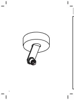
background image

20

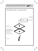
pico plug

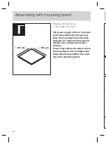
Cut-out:
> 196 x 196 mm

Mounting board for
frameless installation
(fibre-cement plate
with socket)
196 x 196 mm
Thickness: 12.5 mm

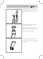
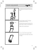
3d pico plug (mounting board)

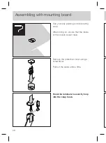
Assembling with mounting board

Summary of Contents for 3d body pico

Page 1: ...3d body pico Montageanleitung Mounting instructions up plug track...

Page 2: ......

Page 3: ...3d body pico Montageanleitung up flat plug track De...

Page 4: ...2...

Page 5: ...3 Sicherheitshinweise 4 Produktbeschreibung 5 Montage body 7 Anhang 43 Informationen 44 Technische Daten 45 Inhalt...

Page 6: ...nen Dieses Zeichen macht Sie auf Situ ationen aufmerksam bei denen Sie direkt in das Licht der LED blicken k nnten Dies kann zu Nachbildern und bei l ngerer Dauer zu Sch di gungen der Augen f hren All...

Page 7: ...uchless Dimmfunktion deaktivierbar Lichtwirkung ber optionale inserts ver nderbar dichroitische Farbfilter zus tzlich einsetzbar Oberfl chenkombinationen von Kopf Pads Arm und Fu frei konfigurierbar P...

Page 8: ...6 3 f V 3 f V 3 f V f V 3 f V...

Page 9: ...griert 9 15 21 29 3d pico flat f r Hohlraum Einputzdose Vorschaltger t extern 3d pico plug f r Hohldecke mit Einputzplatte Vorschaltger t extern f r Hohldecke mit Panel Vorschaltger t extern 37 3d pic...

Page 10: ...8 2 N...

Page 11: ...9 230V AC Netzanschlussleitung Montageplatte hoch Schrauben Hohlraumdose Occhio Konverter Leuchtenk rper Leuchtenkabel mit Stecker Inbusschrauben Cover up 3d pico up Installation auf festem Untergrund...

Page 12: ...dass die Langl cher die gew nschte Ausrichtung haben Bei Wandmontage Gewindel cher senkrecht ausrichten Positionen der Bohrl cher anzeichnen Auf den Verlauf von Stromleitungen achten Zwei L cher 6 mm...

Page 13: ...ilfe eines Schraubendrehers ffnen Konverter b ndig in die Montageplatte einrasten Dabei die Enden der Netzleitung durch die ffnung des Konverters f hren Kabelenden der Netzleitung nach Sche ma an die...

Page 14: ...12 Klappe des Konverters schlie en Stecker des Leuchtenk rpers in die Buchse des LED Konverters stecken Schutzschlauch des Leuchtenarms nicht entfernen Click Click Installation...

Page 15: ...ontageplatte schrauben Dabei darauf achten dass die Rast nasen des Leuchtenk rpers siehe Detail b ndig auf den Abstandshaltern aufliegen Schutzfolie vom Cover abnehmen Cover vorsichtig ber den Leuchte...

Page 16: ...14 H...

Page 17: ...Hohlraumdose bauseitig Montageplatte flach Schrauben Hohlraumdose Leuchtenk rper Inbusschrauben Cover flat externer Konverter 48V DC 230V AC Netzanschlussleitung Leuchtenkabel mit Stecker 3d pico fla...

Page 18: ...Occhio Konverter anschlie en siehe Beiblatt zum Konverter Konverter nach Schema an die Netzlei tung anschlie en LED Anschlusskabel im Konverter einstecken Buchse des LED Anschlusskabels durch die Hoh...

Page 19: ...chlusskabels verbinden Schutzschlauch des Leuchtenarms nicht entfernen Montageplatte an die Hohlraumdose schrauben Dabei die Buchse des LED Anschlusskabels durch die ffnung f hren Darauf achten dass d...

Page 20: ...erten Schrauben Inbus auf die Montageplat te schrauben Schutzfolie vom Cover abnehmen Cover vorsichtig ber den Leuchtenarm f hren Durch Rechtsdrehung arretieren Schutzschlauch vom Leuchtenarm entferne...

Page 21: ...19 l t m...

Page 22: ...20...

Page 23: ...tt 196 x 196 mm Einputzplatte f r rahmenlosen Einbau Faserzementplatte mit Steckpunkt 196 x 196 mm Dicke 12 5 mm 230V AC Netzanschluss leitung 3d pico plug Einputzplatte Montage mit Einputzplatte exte...

Page 24: ...dem Einbau der Einputzplatte durch die ffnung nicht mehr erreichbar Deshalb ist eine Revisionsklappe an anderer Stelle vorzusehen Stromleitungen sind vor Einbau der Einputzplatte zu verlegen und an di...

Page 25: ...iblatt zum Konverter Mitgeliefertes Kabel ggf verl ngern und mit externem Konverter verbinden Konverter nach Schema an die Netzlei tung anschlie en Achtung Die Buchse des Leuchtenanschluss kabels unbe...

Page 26: ...Abbildung kurz nach dem Stecker mit Klebeband verbinden Kabel und Sicherungsseil k nnen nur dann nach der Montage heraus gezogen werden Konverter eines Fremdherstellers anschlie en siehe Beiblatt zum...

Page 27: ...ben vorbohren um die Einputzplatte nicht zu besch digen WARNUNG Der Hersteller weist ausdr cklich darauf hin dass eine nicht fach gerecht installierte Einputzplatte herabfallen kann und eine erhebli c...

Page 28: ...f achten dass die Innensei te des Steckpunkts nicht verschmutzt wird Montage mit Einputzplatte Schutzkappe mithilfe eines Schrauben drehers entfernen Kabelende etwas herausziehen Sicherheitsschlaufe d...

Page 29: ...Kabel und Steckverbindung durch die ffnung zur ckschieben Pico plug in den Steckpunkt einstecken Der Plug rastet in Endstellung ein Sicheren Halt berpr fen i Click 3d pico plug Einputzplatte Buchse d...

Page 30: ...28...

Page 31: ...pico plug Schrauben L nge max 14 mm Bohrung 32 mm Plattenst rke 7 5 15 mm Steckpunkt Distanzscheiben 1 und 1 5 mm 230V AC Netzanschluss leitung 3d pico plug Panel Montage Panel externer Konverter 48V...

Page 32: ...des Panels durch die ff nung nicht mehr erreichbar Deshalb ist eine Revisionsklappe an anderer Stelle vorzusehen Stromleitungen sind vor Einbau des Panels zu verlegen und an die ff nung des Panels her...

Page 33: ...bedingt in die Schutzkap pe einstecken Sicherungsseil und LED Kabel wie in der Abbildung kurz nach dem Stecker mit Klebeband verbinden Kabel und Sicherungsseil k nnen nur dann nach der Montage heraus...

Page 34: ...Abbildung kurz nach dem Stecker mit Klebeband verbinden Kabel und Sicherungsseil k nnen nur dann nach der Montage heraus gezogen werden Konverter eines Fremdherstellers anschlie en siehe Beiblatt zum...

Page 35: ...e heraussteht wie folgt vorgehen Steckpunkt mit so vielen Distanz scheiben unterlegen bis die H lse b ndig mit der Sichtfl che des Panels abschlie t Dabei darauf achten dass die Pins der Distanzscheib...

Page 36: ...usf hren Dabei darauf achten dass die Innensei te des Steckpunkts nicht verschmutzt wird Schutzkappe mithilfe eines Schrauben drehers entfernen Kabelende etwas herausziehen Sicherheitsschlaufe der Leu...

Page 37: ...ntage siehe Anleitung head Kabel und Steckverbindung durch die ffnung zur ckschieben Pico plug in den Steckpunkt einstecken Der Plug rastet in Endstellung ein Sicheren Halt berpr fen i Click Buchse de...

Page 38: ...36 E 1 S 3 2 1 0...

Page 39: ...37 1 oder 3 Phasen Track Adapter Geh use mit cover EUTRAC kompatible 1 oder 3 Phasen Stromschiene 230 V 3d pico track...

Page 40: ...on Leuchtenarm wie in der Abb ausrich ten Track Adapter am Geh use um 90 drehen Achtung Vor der Montage alle stromf hrenden Leitungen vom Stromnetz trennen Cover kr ftig nach unten ziehen wird durch C...

Page 41: ...gew nschten Stelle in die Schiene einsetzen 3 2 1 0 Unbeschrifteten Knebel um 90 im Uhr zeigersinn schlie en Hiermit wird der Track Adapter an den neutralen Leiter angeschlossen Endposition des Knebel...

Page 42: ...ase 2 nur 3 Phasen Track Adapter Einstellknebel um 90 gegen den Uhrzeigersinn drehen Der Track Adapter ist nun an Phase 2 angeschlossen Einstellen auf Phase 3 nur 3 Phasen Track Adapter Einstellknebel...

Page 43: ...er b ndig zur ckschieben wird durch Clips gehalten Schutzfolie von Geh use und body entfernen Der body ist nun fertig montiert head Montage siehe Anleitung head Geh use um 90 schwenken Ausrichtung Par...

Page 44: ...42...

Page 45: ...43 Anhang...

Page 46: ...ung der Leuchte ein trocke nes Mikrofasertuch oder das Occhio Reinigungsmittel verwenden Weitere Fragen beantwortet gerne Ihr Occhio Fachh ndler www occhio de info occhio de Pflegehinweise Info Kontak...

Page 47: ...track Version 2 Anschluss up track 230V AC 50Hz min 22W mit io oder lui head Vorschaltger t Dimmung am head oder up track per Phasenabschnittdimmer Liste plug mit geeignetem Vorschaltger t dimmbar Mat...

Page 48: ...46...

Page 49: ...3d body pico Mounting instructions up flat plug track En...

Page 50: ...2...

Page 51: ...3 Safety precautions 4 Product description 5 Assembling the body 7 Appendix 43 Information 44 Technical data 45 Contents...

Page 52: ...look directly into the light of the LED This may cause an after image ef fect and may result in damage to the eyes if you look at the light directly for prolonged periods General safety precautions Th...

Page 53: ...ng function can be deactivated Lighting effect can be changed through optional inserts dichroitic colour filter can be additionally inserted Surface combinations of head pads stem and base can be conf...

Page 54: ...6 3 f I 3 f E 3 f E f E 3 f I...

Page 55: ...21 29 3d pico flat for hollow ceiling plastering box External power supply unit 3d pico plug for hollow ceiling with mounting board External power supply unit for hollow ceiling with panel External po...

Page 56: ...8 2 m...

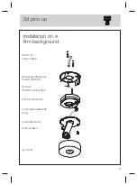
Page 57: ...0 V AC mains cable Mounting plate posi tioned upwards Screws Hollow ceiling box Occhio converter Luminaire body Luminaire cable with plug Allen screws up cover 3d pico up Installation on a firm backgr...

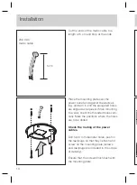
Page 58: ...gated holes are aligned as required When mounting to a wall orient the threaded holes verti cally Mark the positions where the holes are to be drilled Check the routing of the power cables Drill two 6...

Page 59: ...the converter Lock the converter into the mounting plate so that it is fitted flush At the same time guide the ends of the mains cable through the converter opening Connect the ends of the mains cabl...

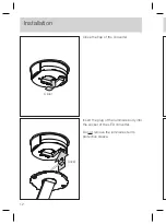
Page 60: ...12 Close the flap of the converter Insert the plug of the luminaire body into the socket of the LED converter Do not remove the luminaire stem s protective sleeve Click Click Installation...

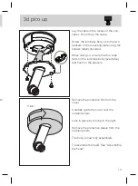
Page 61: ...provided When doing so ensure that the snap tabs on the luminaire body see detail rest flush on the spacers Remove the protective film from the cover Carefully guide the cover over the luminaire stem...

Page 62: ...14 H c...

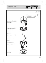
Page 63: ...ling box provided and fitted by customer Flat mounting plate Screws Hollow ceiling box Luminaire body Allen screws flat cover External converter 48 V DC 230 V AC mains cable Luminaire cable with plug...

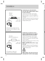
Page 64: ...ox Connecting an external Occhio converter see supplementary sheet for the converter Connect the converter to the mains cable as shown in the wiring diagram Plug in the LED connection cable in the con...

Page 65: ...e LED connection cable Do not remove the luminaire stem s protective sleeve Screw the mounting plate to the hollow ceiling box As you do so guide the socket of the LED connection cable through the ope...

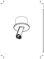
Page 66: ...g plate using the screws Allen provided Remove the protective film from the cover Carefully guide the cover over the luminaire stem Lock in place by turning to the right Remove the protective sleeve f...

Page 67: ...19 ng...

Page 68: ...20...

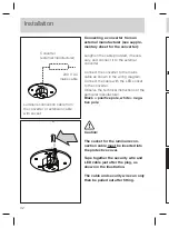
Page 69: ...96 x 196 mm Mounting board for frameless installation fibre cement plate with socket 196 x 196 mm Thickness 12 5 mm 230 V AC mains cable 3d pico plug mounting board Assembling with mounting board Exte...

Page 70: ...h the opening after the mounting board has been installed An inspection flap should therefore be provided at another location Power lines should be routed before the mounting board is installed and th...

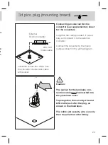
Page 71: ...r the converter Lengthen the cable provided if neces sary and connect it to the external converter Connect the converter to the mains cable as shown in the wiring diagram Caution The socket for the lu...

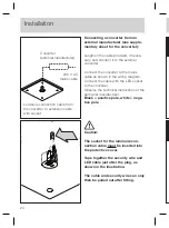
Page 72: ...s shown in the illustration The cable and security wire can only then be pulled out after fitting Connecting a converter from an external manufacturer see supple mentary sheet for the converter Length...

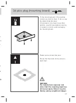
Page 73: ...re drill holes before screwing it in place in order to avoid damaging the mounting board WARNING The manufacturer expressly indi cates that if the mounting board has not been properly fitted it may fa...

Page 74: ...ng work When doing so ensure that the inside of the socket is kept clean Assembling with mounting board Remove the protective cover using a screwdriver Pull out the cable ends a little Hook the lumina...

Page 75: ...e cable and plug connection back through the opening Insert the pico plug into the socket The plug clicks into place in its end position Check that it is held securely Click 3d pico plug mounting boar...

Page 76: ...28...

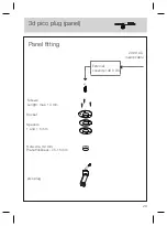
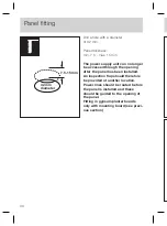
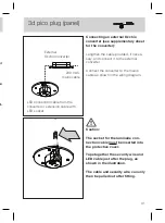
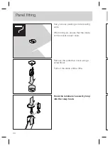
Page 77: ...29 pico plug Screws Length max 14 mm Hole dia 32 mm Plate thickness 7 5 15 mm Socket Spacers 1 and 1 5 mm 230 V AC mains cable 3d pico plug panel Panel fitting External converter 48 V DC...

Page 78: ...ing after the panel has been installed An inspection flap should therefore be provided at another location Power lines should be routed before the panel is installed and these should be guided to the...

Page 79: ...into the protective cover Tape together the security wire and LED cable just after the plug as shown in the illustration The cable and security wire can only then be pulled out after fitting Connectin...

Page 80: ...s shown in the illustration The cable and security wire can only then be pulled out after fitting Connecting a converter from an external manufacturer see supple mentary sheet for the converter Length...

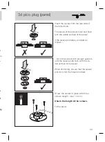
Page 81: ...leeve protrudes proceed as follows Shim the socket with enough spacers until the sleeve ends flush with the vis ible surface of the panel When shimming ensure that the spacer pins lock into the holes...

Page 82: ...painting and decorating work When doing so ensure that the inside of the socket is kept clean Remove the protective cover using a screwdriver Pull out the cable ends a little Hook the luminaire s sec...

Page 83: ...ssembling the head Push the cable and plug connection back through the opening Insert the pico plug into the socket The plug clicks into place in its end position Check that it is held securely Click...

Page 84: ...36 E 1 b 3 2 1 0...

Page 85: ...37 1 or 3 phase track adapter Housing with cover EUTRAC compatible 1 or 3 phase bus bar 230 V 3d pico track...

Page 86: ...luminaire stem as shown in the illustration Turn the track adapter on the housing 90 Caution Before fitting disconnect all current carrying lines from the mains supply Firmly pull the cover downwards...

Page 87: ...t the spotlight into the track at the desired position 3 2 1 0 Lock the blank toggle by turning it 90 clockwise This connects the track adapter to the neutral wire Final position of the toggle Paralle...

Page 88: ...2 adjustment 3 phase track adapter only Turn the adjusting toggle 90 anticlockwise The track adapter is now connected to phase 2 Phase 3 adjustment 3 phase track adapter only Pull out the adjusting to...

Page 89: ...back on so it is flush it is held in place by clips Remove the protective film from the housing and body The body is now fully assembled To assemble the head See Assembling the head Swivel the housing...

Page 90: ...42...

Page 91: ...43 Appendix...

Page 92: ...luminaire use a dry microfi bre cloth or the Occhio cleaning agent Your Occhio specialist retailer will gladly answer any other questions www occhio de info occhio de Care instructions Information co...

Page 93: ...ety class Connection up track 230 V AC 50 Hz min 22 W with io or lui head Power supply unit Dimming On the head or up track By trailing edge phase cut dimmer for a list of compatible dimmers see www o...

Page 94: ...46...

Page 95: ......
Page 96: ...H Wiener Platz 7 D 81667 M nchen Fon 49 89 44 77 86 30 Fax 49 89 44 77 86 39 info occhio de www occhio de 2016 06 Irrt mer und technische nderungen vorbehalten Subject to errors and technical change O...

Reviews: