


System instructions OBO isCon
®
EN | 57
Mounting variants
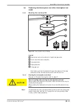
6 Mounting variants
6 1
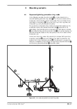
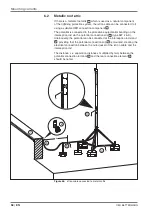
Separate lightning protection ring cable
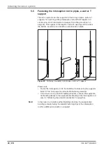
In the following example, the isCon cable
1
is to be connected to a
stand-off lightning protection ring cable
2
. For this, we recommend the
interception rod stand with external isCon cable. This is shortened to the
right height using spacers
3
(type isCon DH), run to the ring cable and
connected, e.g. using Vario quick connectors.
The potential is connected to the protective equipotential bonding on the
interception rod via the potential connection clip
4
(type 927 2 6-K).
Alternatively, the potential can be connected at the interception rod stand
5
, providing that the potential connection clip
4
is mounted, creating the
electrical connection between the outer jacket of the isCon cable and the
interception rod.
At the end of the isCon cable, the potential is connected with a potential
connection terminal
6
(type isCon PAE) to the lightning protection ring
cable in front of the connection element
7
. The distance x (= separation
distance s multiplied by two) between the potential connection terminal
6
and the rear connection element
7
should be noted.
x
Rd 8
1
4
3
2
6
5
7
Figure 65:
isCon cable connected to stand-off ring cable
Summary of Contents for isCon 750 LGR
Page 1: ...03 2014 EN isCon System instructions...
Page 65: ...System instructions OBO isCon EN 65 Own notes...
Page 66: ...OBO BETTERMANN 66 EN...
Page 67: ......


