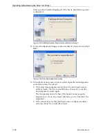
Operating & Maintaining the Eden 3-D Printer
7–22
DOC-00260 Rev. A1
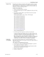
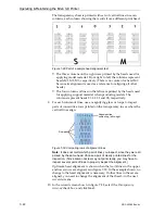
The
transparency
sheet
is
printed
with
sets
of
vertical
lines
in
seven
columns,
each
column
showing
the
results
from
a
different
head.
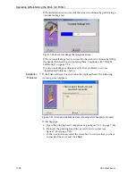
Figure 7-29:Part of a sample head-alignment test
•
The
three
columns
on
the
right
were
printed
by
the
heads
used
for
applying
model
material.
From
right
to
left,
the
columns
represent
heads
M1,
M2,
M3,
respectively.
(There
is
no
column
for
head
M0
because
its
alignment
is
used
as
a
reference
for
aligning
all
other
heads.)
•
The
four
columns
of
lines
on
the
left
were
printed
by
the
heads
used
for
applying
support
material
when
producing
models.
The
columns
represent
heads
S3,
S2,
S1
and
S0,
respectively.
9. For
each
column
of
lines,
use
a
magnifying
glass
or
loupe
to
inspect
pairs
of
consecutive
rows
printed
on
the
transparency
to
see
where
the
vertical
lines
align.
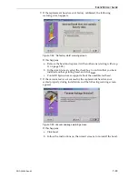
Figure 7-30:Comparing rows of alignment lines
Note:
It does not matter which pair of lines you inspect, since they were all
printed by the same head. Choose a pair of clearly printed lines for the
inspection. (Since some nozzles may not print clearly, you may have to
inspect several pairs of lines to properly inspect the alignment.)
Optimum
head
alignment
is
shown
when
the
fourth
lines
in
the
upper
and
lower
rows
are
aligned,
as
in
In
the
example
shown,
no
change
to
the
head
alignment
is
necessary.
If
other
lines
in
the
set
are
aligned,
you
need
to
change
the
alignment
of
that
head—in
the
next
wizard
screens.
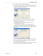
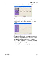
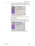
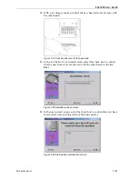
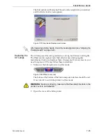
10. In
the
wizard
screen
shown
in
28,
select
the
Transparency
removed
check
box,
and
click
Next
.
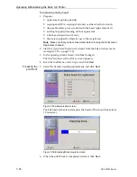
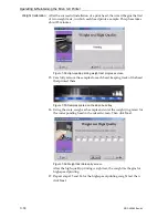
Alignment-line
numbering, left-to-right
Row pairs

