background image

11 

- GB - 

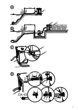
Combination with Proficlear module filter (B) 

Operation of Bitron 550 LM (1) is only possible in systems with integrated pump. A maximum of three module filters 
M2-M5 (2) may be installed downstream of the UVC clarifying unit. Please read the documentation covering the Profic-
lear module filter system. 


Installation (C-K) 

As standard, the unit is equipped with a 2“ connection at the inlet and a DN 150 connection at the outlet. 

Installation of the sludge drain (C) 

The dirt water might contain fish manure and has to be disposed of in accordance with the valid legal regulations. For 
this purpose, bond a DN 50 pressure pipe (4) to the dirt water drain (3). Lay the pipe (4) with a 20 mm/m gravity. 

Inlet with a 2“ or OD 63 connection (D) 

2“ connection: Screw the stepped hose adapter (7) with the sealing ring (8) on the inlet (9). Slide the hose clip (6) over 
the hose (5), plug the hose (5) on the stepped hose adapter (7), and secure the hose (5) on the stepped hose adapter 
(7) by means of the hose clip (6). 
OD 63 connection: Shorten the stepped hose adapter (7) and screw on the inlet (9) with the sealing ring (8). Glue the 
OD 63 pipe (10) with the stepped hose adapter (7). 

ND 100 connections (E-K) 

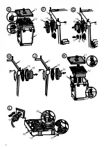
Preparatory work (E): The unit (1) must be converted to be able to use the ND 100 connection. Remove the four cap 
nuts from the cover, remove the cover (11), loosen the engagement hooks (13) and completely remove the inner cover 
(12). 
Inlet with DN 100 connection (F, G): Remove the 6 screws from the inside of the container, then take out the plug 150 
(14) including sealing ring 150 (15). Tightly fasten the inlet socket 100 (16) and the sealing ring 150 (15) using the 6 
screws on the inside of the container. Close the 2“ inlet (9) using the threaded cap (17) and the sealing ring (8). Con-
nect a ND 100 pipe and route it as straight as possible (maximum 45° bends) and well protected. 
Outlet with ND 100 connection (H, J): Remove the 6 screws from the inside of the container, then take out the outlet 
plug 100 (18) including sealing ring 150 (15). Tightly fasten the outlet socket 100 (16) and the sealing ring 150 (15) 
using the 6 screws on the inside of the container.  
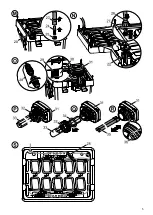
Final work (K): Insert the complete inner cover (12) into the container and arrest using the engagement hook (13). Fit 
the cover (11) and secure cover with four cap nuts. 

Outlet connection 

Connect a pipe ND 150 or ND 100 with the least possible bend (maximum 45° bends) and route well protected, with a 
minimum incline of 10 mm/m. 


Start-up (L) 

Ensure that the slide valve (22) of the sludge drain is always closed when the unit is in operation! Danger of completely 
emptying the pond!


Prior to start-up, check that all hooks (13) at the inner covers are firmly closed and that all connected hoses and pipes 
are correctly seated. 


Attention! Dangerous electrical voltage. 
Possible consequences:

 Death or severe injury. 

Protective measures:

 Disconnect the power plug (19) prior to reaching into the water and commencing 

work. 


Switching on 

Start with connecting the pump and checking all connections for leaks. Subsequently, switch the UVC clarifying unit on. 
The UVC clarifying unit switches on automatically when power connection is established. Whether or not the UVC lamp 
is lit can be checked through the inspection window (21). The luminosity is insufficient in heavily soiled water, making a 
visual check impossible. Remedy: Switch off the pump and wait until the sludge in the water has settled. Once the 
sludge has settled, switch the pump on again. 

Notes 

  The water level indicator (20) is intended to check the water level in the container. When the float switch is at its 

maximum raised position, the water builds up in the container, and the filter system must be cleaned immediately. 

  Once the start-up is completed, close the container (1) with the cover (11) and secure with four cap nuts. 

  When a Proficlear module filter M2-M5 is connected downstream, operate the Bitron 550 LM for approx. one week 

with the UVC lamps switched off to allow bacteria cultures to form on the bioballs. 

Switching off 

Switch off the pump first, then disconnect the power plug (19) from the UVC clarifying unit. 


Summary of Contents for Bitron 550 LM

Page 1: ...D Gebrauchsanweisung GB Operating instructions F Notice d emploi NL Gebruiksaanwijzing E Instrucciones de uso Bitron 550 LM 30132 04C...

Page 2: ...absorb e Lampe UVC Raccorde ment NL Afmetingen Gewicht Ingang Uitgang Doorstroomhoeveelheid Nominale spanning Vermogens opname UVC lamp Voedings kabel E Dimensiones Peso Entrada Salida Caudal con Ten...

Page 3: ...3...

Page 4: ...4...

Page 5: ...5...

Page 6: ...iederspannungsrichtlinie 73 23 EWG erkl ren wir die Konformit t Folgende harmonisierte Normen wurden angewandt EN 55015 EN 60598 1 EN 60598 2 EN 61000 3 2 EN 61000 3 3 EN 61547 Unterschrift Sicherheit...

Page 7: ...Bestimmungen entsorgt werden Dazu eine Druckrohrleitung DN 50 4 mit dem Schmutzwasserablauf 3 verkleben Die Rohrlei tung 4 mit einem Gef lle von 20 mm m verlegen Eingang mit 2 oder DA 63 Anschluss D 2...

Page 8: ...hrter Reihenfolge wieder montieren so dass sich der Schwimmer 24 im Geh use 23 frei bewegen kann Beh lter reinigen N Den Absperrschieber 22 des Schmutzablaufs ffnen und warten bis das Teichwasser abge...

Page 9: ...rpr fen UVC Lampe leuchtet nicht UVC berhitzt Nach Abk hlung automatische Einschaltung vom UVC Pumpenleistung passt nicht Pumpenleistung anpassen Wasser ist extrem verschmutzt Algen und Bl tter aus de...

Page 10: ...wer supply to all units used in the water Correct electrical installation Electrical installations at ponds must meet the international and national regulations valid for installers Electrical install...

Page 11: ...utlet plug 100 18 including sealing ring 150 15 Tightly fasten the outlet socket 100 16 and the sealing ring 150 15 using the 6 screws on the inside of the container Final work K Insert the complete i...

Page 12: ...artz glass 33 for damage and clean its outer face with a moist cloth Note Condensate could collect in the quartz glass because of the vertical installation position of the UVC Remove the quartz glass...

Page 13: ...es germes pathog nes sont limin s efficacement Le Bitron 550 LM dispose de raccordements variables d une indication de niveau d eau pour le contr le du taux d encrassement d un thermom tre pour le con...

Page 14: ...raccordement au secteur Le c ble de raccordement au secteur ne peut pas tre remplac Ne jamais utiliser l appareil sans d bit d eau L appareil en serait d truit Ne jamais refouler des liquides autres...

Page 15: ...m s et si tous les tuyaux raccord s et toutes les conduites raccord es sont fix s correctement Attention Tension lectrique dangereuse Cons quences ventuelles mort ou blessures graves Mesures de protec...

Page 16: ...que des lampes dont la d signation et la puissance correspondent aux indications fournies sur la plaque signal tique Remarque en raison de la position d installation verticale de l UVC de la condensa...

Page 17: ...eden met dit apparaat mogen uitsluitend verricht worden als ze conform de onderhavige handleiding zijn Toepassing Door de UV behandeling die het UVC voorzuiveringsapparaat Bitron 550 LM uitvoert wordt...

Page 18: ...beschadigingen uitgesloten zijn Draag til of trek het apparaat niet aan de stroomkabel De stroomkabel kan niet worden vervangen Gebruik het apparaat nooit zonder dat er water doorheen stroomt Dan raa...

Page 19: ...het gebruik of alle bevestigingshaken 13 op het binnendeksel goed vastgeklikt zitten en of alle aangesloten slangen en buizen goed en stevig vastzitten Let op Gevaarlijke elektrische spanning Mogelijk...

Page 20: ...lleen lampen waarvan de omschrijving en het aangegeven vermogen overeenkomen met die op het typeplaatje Opmerking doordat de UVC verticaal gemonteerd is kan zich condenswater in het kwartsglas ophopen...

Page 21: ...leta del agua de estanque con el equipo preclarificador UVC Bitron 550 LM se eliminan de forma efectiva las algas as como las bacter as y los g rmenes pat genos El Bitron 550 LM est provisto de conexi...

Page 22: ...rte ni tire el equipo por la l nea de conexi n de red La l nea de conexi n de red no se puede cambiar No opere nunca el equipo sin circulaci n de agua Esto destruir a el equipo No transporte nunca otr...

Page 23: ...e vac e el estanque Antes de la puesta en servicio compruebe si est n cerrados bien todos los ganchos de retenci n 13 en la tapa interior y asentados correctamente todos los tubos flexibles y tuber as...

Page 24: ...s cuya denominaci n y especificaci n de potencia se correspondan con las especificaciones en la placa de datos t cnicos Nota Por el montaje vertical del UVC se puede acumular agua condensada en el cri...

Page 25: ...UVC El cuadal de la bomba no adecuado Adapte el caudal de la bomba El agua est extremadamente sucia Elimine las algas y hojas del estanque y cambie el agua El agua no se aclara Exceso de peces y anim...

Page 26: ...gel Tenir compte du paragra phe Stockage Entrepo sage pour l hiver Prot ger contre les rayons directs du soleil La lampe est pr vue pour une fixation directe sur des surfaces de fixation d une inflamm...

Page 27: ...27...

Page 28: ...28...

Reviews: