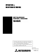
background image

14

Glowplug leads

Fig.12

Switch should have 
sufficient capacity.

The plug leads are fitted with special snap-on connectors 
that ensure firm contact with O.S. plug. They are a "click" fit 
and are not suitable for use with most other makes of 
glowplug.

The earth (ground) lead is fitted with a plug terminal which 
should be connected to the engine by means of one of the 
mounting screws.
Make sure that no part of the wiring touches the cylinder 
head or cooling fins.

Keep wiring away from the fuel tank where it might cause a 
fire in the event of a short-circuit.

Fig.13

Install Ni-Cd battery in the fuselage, and switch on or off by 
means of transmitter. (On-board battery)

1.2 volt Ni-Cd battery with
more than 6 Ah capacity.

If glowplug leads are extended together as a single cable, 
use heavier wire, e.g. 2.0 mm  multi-strand copper core as 
supplied for earth lead.

2

2

2.0mm

Earth lead

Fasten to the
motor mount.

Glowplug re-heat

Under normal conditions, the FT-160 will idle sufficiently 
slowly with the throttle closed to permit a safe landing 
approach. However, if conditions (atmospheric, fuel, tank 
location etc.) are unfavourable, there may be a tendency for 
one cylinder to cease firing if the engine is throttled down to a 
very low idling speed. This can be prevented by installing a 
small on-board Ni-Cd battery which will automatically re-heat 
the glowplugs when the engine is throttled down to idling 
speed (Fig.12). A suitable switch should be installed so that it 
is actuated by the throttle servo only when the engine is 
throttled down. Safe idling speeds of less than 1,800 rpm may 
be obtained in this way and without undue drain on the 
battery. 

15

Model engine fuel is poisonous. Do not allow it to 
come into contact with the eyes or mouth. Always 
store it in a clearly marked container and out of the 
reach of children.

Model engine fuel is also highly flammable. Keep it 
away from open flame, excessive heat, sources of 
sparks, or anything else which might ignite it. Do not 
smoke, or allow anyone else to smoke, near to it.

Reminder!

Fuel
The FT-160 should be operated on a methanol based fuel 
containing not less than 18% (volumetric) castor oil, or a top 
quality synthetic lubricant (or a mixture of both), plus a small 
percentage (5-20%) of nitromethane for improved flexibility 
and power.

FUEL AND LUBRICATION

Lubrication

All parts of the FT-160 are automatically lubricated by the oil 
content of the fuel mixture.

The crankcase breather hole is located at the side of the 
engine and is fitted with a brass nipple. (See photo 3 on page 
7.) Fit a length of silicone tubing of approx. 2.5-3mm I.D. to 
this nipple to conduct away the small amount of oil that 
escapes through the breather.

Make a habit of draining out the excess oil in the crankcase 
at the end of each flying session. Leaving contaminated oil in 
the crankcase for a long time will cause rust. Also, residual 
castoroil will tend to solidify and lock the engine. Inject 
corrosion-inhibiting oil into the crankcase to neutralize the 
effects of any remaining contaminants.

STARTING

Precautions
For safety, please observe the following instructions before 
starting the engine.

Start the engine by turning the propeller counter-clockwise 
(i.e. normal running direction).

Do not start the engine with the throttle fully opened, 
otherwise the model will tend to move forward suddently due 
to the strong thrust of the propeller. Hold both wings of the 
model when starting the engine.

Do not carry out carburetor adjustments (except needle-
valve adjustment) while engine is running.

Use a high-torque electric starter.

Starting procedure is as follows:

Open the needle-valve 3 to 3.5 turns from the fully closed 
position (Fig.14).

1.

Fig.14

open 3 to 3.5 turns.

Summary of Contents for FT-160

Page 1: ...s supplied with the aircraft radio control equipment etc are accessible for checking at the same time Horizontally opposed twin cylinder overhead valve four stroke cycle 1 2 4 5 6 7 8 10 10 11 12 13 14 15 18 18 19 19 21 22 22 23 25 26 27 28 29 30 SAFETY INSTRUCTIONS AND WARNINGS ABOUT YOUR O S ENGINE INTRODUCTION TOOLS AND ACCESSORIES ENGINE PARTS NAME INSTALLATION PROPELLER FUEL TANK GLOWPLUGS GL...

Page 2: ...de Run your engine only in an open area Model engines generate considerable heat Do not touch any part of your engine until it has cooled Contact with the muffler silencer cylinder head or exhaust header pipe in particular may result in a serious burn 3 NOTES This engine was designed for model aircraft Do not attempt to use it for any other purpose Mount the engine in your model securely following...

Page 3: ...ne running be especially cautious Keep the propeller pointed away from you and walk well clear of spectators Warning Immediately after a glowplug ignition engine has been run and is still warm conditions sometimes exist whereby it is just possible for the engine to abruptly restart if the propeller is casually flipped over compression WITHOUT the glowplug battery being reconnected Remember this if...

Page 4: ...e Carburetor Exhaust Pipe Propeller Nut Cylinder Head Left No 1 Cylinder Right No 2 Cylinder Photo 2 Aluminum tube Aluminum tube is not supplied with the engine 7 Push Rod Cover Choke Valve Intake Pipe Left Photo 3 Fuel Inlet Intake Pipe Right Rear Housing Intake Manifold Breather Nipple ...

Page 5: ...t by reversing the hexagon nut nd cap screw Unscrew the cap screw while holding the hexagon nut with 6mm wrench and re fit the lever to required location If the rod is too long reduce it to required length A needlessly lengthy rod may vibrete The rod should be as short as possible or have its outer end supported Fig 3 Set screw Choke lever Hex nut Cap screw Choke rubber pad Fuel inlet The fuel inl...

Page 6: ...mly after retightening the propeller nut NOTE 11 Ream the propeller shaft hole to 12mm bore with an appropriate reamer checking that the hole is exactly centered Install the prop to the engine shaft followed by the retaining washer and prop nut and tighten firmly with a 17mm wrench not supplied 1 2 3 Add the special tapered and slotted locknut and secure with a 12mm wrench while holding the prop n...

Page 7: ... to a conveniently located common external point on the fuselage This can either be a terminal with a separate terminal for the earth ground lead Fig 10 or a suitable socket or jack with connections for both glowplug and earth ground leads Fig 11 Note that the earth ground lead supplied is much heavier 2 0 mm multi strand copper core than the plug leads as this has to have the capacity to carry th...

Page 8: ...ways store it in a clearly marked container and out of the reach of children Model engine fuel is also highly flammable Keep it away from open flame excessive heat sources of sparks or anything else which might ignite it Do not smoke or allow anyone else to smoke near to it Reminder Fuel The FT 160 should be operated on a methanol based fuel containing not less than 18 volumetric castor oil or a t...

Page 9: ...l from penetrating the airframe structure Release the choke control and immediately turn the propeller c o u n t e r c l o c k w i s e several times so that fuel is drawn well into the cylinders Fig 19 4 Fig 19 17 Set the throttle valve approximately 1 4 open from the fully closed position Fig 20 5 Fig 20 Fully open Fully closed Set at this position Starting with an electric starter Fig 21 6 Fig 2...

Page 10: ...valve at 500 1 000r p m lower than maximum r p m setting and run approx 10 seconds It is suggested to use a tachometer Open the needle valve at approx 1 000r p m lower than above setting and run approx 20 seconds Repeat above procedure while increasing the setting 1 r p m gradually for approx 10 minutes Keep the throttle fully open using only the needle valve to change r p m Prolonged running in o...

Page 11: ...ngine stopping is obtained The position where the lowest possible r p m with steady running is obtained Approx 40 open from maximum r p m setting Yes No Yes Engine stops Engine stops Disconnect the glowplugs from the battery Make sure that all 2 cylinders are firing Make sure glowplug heat is switched The engine hesitates before picking up to full speed or appears to run at medium speed with reduc...

Page 12: ...ated at the centre The pin is seen if the throttle lever is removed mark Throttle lever Carefully turn the screw in the direction of the mark with the screw driver supplied until it stops then turn back again exactly two revolutions NOTE If an on board glowplug re heat system is fitted mixture adjustment at idling speed should be carried out with this in operation 22 FLIGHT It is necessary to warm...

Page 13: ...point both valves should be closed If the prop driver drive hub of your engine is engraved with a letter T this mark should now be at the top The standard valve clearance on both inlet and exhaust valves is between 0 04mm and 0 1mm 0 0015 0 004 inch measured between valve stem and rocker arm Use the 0 04mm and 0 1mm feeler gauges to check clearances See Fig 29 Fig 29 0 04mm Feeler Gauge Rocker Arm...

Page 14: ... replace rocker box cover 6 Remember Excessive valve clearance will cause loss of power due to valve s not opening sufficiently On the other hand a total loss of clearance may cause difficult starting due to valves not closing properly resulting in loss of compression Re tighten locknut while holding adjusting screw stationary Fig 33 4 Hold at the screw head Fig 33 Tighten Locknut ...

Page 15: ...3 13 1 13 2 14 15 16 16 1 16 2 16 3 17 18 19 20 21 22 23 24 25 26 27 28 29 29 1 30 31 32 33 34 35 36 37 38 39 Description Code No No Description Code No No Screw Set Rocker Cover Rocker Support Assembly Rocker Support Rocker Arm Retainer 2pcs Rocker Arm Assembly 1pair Rocker Arm 1pc Tappet Adjusting Screw Exhaust Pipe Assembly Exhaust Pipe Exhaust Pipe Lock Nut Valve Assembly 1pair Valve 1pc Valve...

Page 16: ... choke valve assembly is not included in the carburettor complete Type of screw C Cap Screw M Oval Fillister Head Screw F Flat Head Screw N Round Head Screw S Set Screw CARBURETOR EXPLODED VIEWS PARTS LIST The specifications are subject to alteration for improvement without notice N M3x22 S M3x3 S M3x3 S M3x3 S M3x3 1 2 2 1 3 1 3 4 1 4 5 6 7 7 1 8 10 10 1 10 2 11 9 9 1 9 3 9 2 9 4 9 6 9 5 9 7 29 R...

Page 17: ...120 76 THREE VIEW DRAWING Dimensions mm Specifications Displacement Bore Stroke PracticalR P M Output Weight C Copyright 2004 by O S Engines Mfg Co Ltd All rights reserved Printed in Japan 60090531 040501 TEL 06 6702 0225 FAX 06 6704 2722 6 15 3 Chome Imagawa Higashisumiyoshi ku Osaka 546 0003 Japan URL http www os engines co jp ...

Reviews: