


UM10310_1
© NXP B.V. 2008. All rights reserved.
User manual
Rev. 01 — 1 December 2008
44 of 139
NXP Semiconductors
UM10310
P89LPC9321 User manual
The Real-time Clock is a 23-bit down counter. The clock source for this counter can be
either the CPU clock (CCLK) or the XTAL1-2 oscillator. There are five SFRs used for the
RTC:
RTCCON —
Real-time Clock control.
RTCH —
Real-time Clock counter reload high (bits 22 to 15).
RTCL —
Real-time Clock counter reload low (bits 14 to 7).
RTCDATH —
Real-time clock data register high.
RTCDATL —
Real-time Clock data register low.
The Real-time clock system timer can be enabled by setting the RTCEN (RTCCON.0) bit.
The Real-time Clock is a 23-bit down counter (initialized to all 0’s when RTCEN = 0) that is
comprised of a 7-bit prescaler and a 16-bit loadable down counter. When RTCEN is
written with logic 1, the counter is first loaded with (RTCH, RTCL, ‘1111111’) and will count
down. When it reaches all 0’s, the counter will be reloaded again with (RTCH, RTCL,
‘1111111’) and a flag - RTCF (RTCCON.7) - will be set.
The 16-bit counter portion of the RTC is readable by reading the RTCDATH and
RTCDATL registers.
8.1 Real-time clock source
RTCS1/RTCS0 (RTCCON[6:5]) are used to select the clock source for the RTC if either
the Internal RC oscillator or the internal WD oscillator is used as the CPU clock. If the
internal crystal oscillator or the external clock input on XTAL1 is used as the CPU clock,
then the RTC will use CCLK as its clock source.
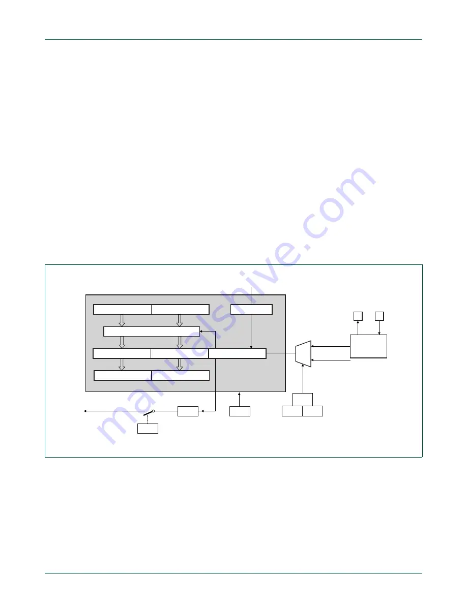
Fig 20. Real-time clock/system timer block diagram.
RTCH
RTCL
RTCDATH
RTCDATL
RTC Reset
Power-on
reset
Reload on underflow
MSB
LSB
÷
128
23-bit down counter
Wake-up from power-down
Interrupt if enabled
(shared with WDT)
002aae091
ERTC
RTCF
RTC underflow flag
RTCEN
RTC enable
7-bit prescaler
RTCS1 RTCS2
RTC clk select
CCLK
internal
oscillators
LOW FREQ.
MED. FREQ.
HIGH FREQ.
XTAL2
XTAL1


