


NXP Semiconductors
UMxxxxx
Install Guide
All information provided in this document is subject to legal disclaimers.
Preliminary 1
— September 6, 2013
© NXP B.V. 2013. All rights reserved.
17 of 70
Development Board (OM13260) is connected.
Note:
To restore operation as a “Trade Show” demo,
the firmware on the Fm+ Development Board
(OM13260) must be reset to “Trade Show” mode by installing the correct firmware. (See section 4.8).
4.8
OM13260 Firmware Installation
Access to the on board MCU firmware is made through the USB port (CN5). The MCU is also accessible
from the JTAG connector (CN19) should it be necessary to recover from a “bricked” board (not very
likely as the MCU boot-loader code is in protected memory).
1.
Connect a USB cable from the PC USB port to CN5.
Note: Two green LEDs are on (D4 for VUSB and D5 for 3V3)
2.
Install the ISP (JP6) jumper to put the MCU into In-System Programming mode
3.
Install and then remove RST (JP4) jumper to reset the MCU
4.
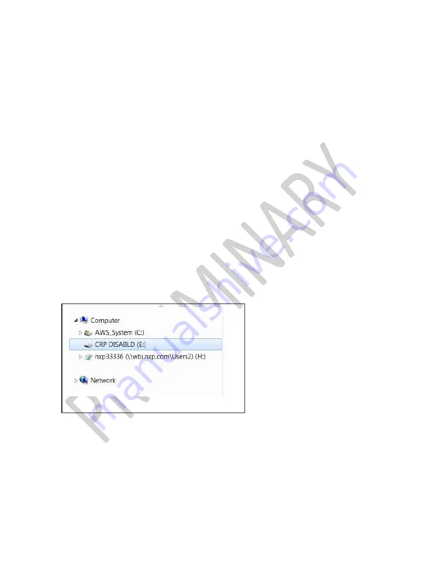
The MCU will enumerate on the PC as shown in Fig 4.12 and Fig 4.13
5.
Delete the file on the MCU (size may vary - up to 32kB)
6.
Copy the new firmware file to the MCU as shown in Fig 4.14
7.
Remove the ISP (JP6) jumper
8.
Install and then remove RST (JP4) jumper to reset the MCU
Note:
The
green LED (D8) is blinking. This is the ‘Heart Beat’ to show the MCU is alive
Fig 4.12 Fm+ Development Board MCU in ISP (Win7 OS)
Summary of Contents for OM13260
Page 71: ......