


Specifications
MIMXRT1050 EVK Board Hardware User’s Guide, User's Guide, Rev. 2, 03/2018
NXP Semiconductors
9
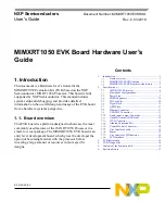
Figure 5. Power Control Diagram
NOTE
Power Control Diagram described in MIMXRT1050 EVK Board is true for A0 silicon For A1
silicon, DCDC_IN is expected to be powered with other domains together.
In the other word, for A0 silicon the DCDC_IN is powered with LDO (Path 1). And for A1 silicon, it
is expected to be powered with DC/DC (Path 2).
For A0 silicon, please following above power logic as if not power the SNVS together with
DCDC_IN, the on chip DCDC module will not power up correctly.
The power rails on the board are shown in
Table
5.
Table 5.
Power Rails
Power Rail
MIN
(V)
TYP
(V)
MAX
(V)
Description
VDD_SOC_IN
0.925
--
1.26
Core supplies input voltage
VDD_HIGH_IN
3
3.3
3.6
VDD_HIGH_IN supply voltage
DCDC_IN
3
¹
3.3
¹
3.6
¹
Power for DCDC