NXP Semiconductors MIMXRT1050 Hardware User'S Manual Download Page 6

Specifications 

MIMXRT1050 EVK Board Hardware User’s Guide, User's Guide, Rev. 2, 03/2018 


NXP Semiconductors 


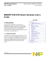
Figure 3.  Overview of the MIMXRT1050 EVK Board (Back side) 

2.1.  i.MX RT1050 Processor 

The i.MX RT1050 is a new processor family featuring NXP's advanced implementation of the ARM 
Cortex-M7 Core. It provides high CPU performance and best real-time response. The i.MX RT1050 
provides various memory interfaces, including SDRAM, Raw NAND FLASH, NOR FLASH, 
SD/eMMC, Quad SPI, HyperBus and a wide range of other interfaces for connecting peripherals, such 
as WLAN, Bluetooth

, GPS, displays, and camera sensors. Same as other i.MX processors, i.MX 

RT1050 also has rich audio and video features, including LCD display, basic 2D graphics, camera 
interface, SPDIF and I2S audio interface.   
The i.MX RT1050 applications processor can be used in areas such as industrial HMI, IoT, motor 
control and home appliances. The architecture's flexibility enables it to be used in a wide variety of other 
general embedded applications too. The i.MX processor provides all interfaces necessary to connect 
peripherals such as WLAN, Bluetooth™, GPS, camera sensors, and multiple displays. 
The more detail information about i.MX RT1050 can be found in the 

Datasheet and Reference manual

Summary of Contents for MIMXRT1050

Page 1: ...d which gives the developer the option of becoming familiar with the processor before investing a large amount or resources in more specific designs NXP Semiconductors Document Number MIMXRT1050EVKHUG...

Page 2: ...nnector Ethernet 10 100 Mbit s Ethernet Connector PHY Chip KSZ8081RNB USB USB 2 0 OTG Connector USB 2 0 Host Connector Audio Connector 3 5 mm Audio Stereo Headphone Jack Board Mounted Microphone Left...

Page 3: ...ents The MIMXRT1050 EVK contains the following items MIMXRT1050 EVK Board USB Cable Micro B 1 3 MIMXRT1050 EVK Board revision history EVK Rev A Prototype EVK Rev A1 2 Pilot Board EVK Rev A3 4 5 Mass P...

Page 4: ...ecifications This chapter provides detailed information about the electrical design and practical considerations of the EVK Board and is organized to discuss each block in the following block diagram...

Page 5: ...Specifications MIMXRT1050 EVK Board Hardware User s Guide User s Guide Rev 2 03 2018 NXP Semiconductors 5 Figure 2 Overview of the MIMXRT1050 EVK Board Front side...

Page 6: ...onnecting peripherals such as WLAN Bluetooth GPS displays and camera sensors Same as other i MX processors i MX RT1050 also has rich audio and video features including LCD display basic 2D graphics ca...

Page 7: ...3 shows the typical Boot Mode and Boot Device settings Table 3 Typical Boot Mode and Boot Device settings SW7 1 SW7 2 SW7 3 SW7 4 Boot Device OFF ON ON OFF Hyper Flash OFF OFF ON OFF QSPI Flash ON OF...

Page 8: ...VK board is shown in the following figure For A0 silicon It will power up SNVS and DCDC_IN together firstly then PMIC_REQ_ON will be switched on to enable external DC DC to power up other power domain...

Page 9: ...d for A0 silicon the DCDC_IN is powered with LDO Path 1 And for A1 silicon it is expected to be powered with DC DC Path 2 For A0 silicon please following above power logic as if not power the SNVS tog...

Page 10: ...3 3V mode 1 65 1 8 1 95 Power for GPIO in SDIO2 bank 1 8V mode NVCC_EMC 3 3 3 3 6 IO supply for GPIO in EMC bank 3 3 V mode 1 65 1 8 1 95 IO supply for GPIO in EMC bank 1 8 V mode NVCC_GPIO 3 3 3 3 6...

Page 11: ...hanged 2 7 1 EVKA Settings Step1 The onboard HyperFlash should be removed otherwise it will impact the QSPI Flash read and write timing Step2 Weld 0 resistor to the pad from R153 to R158 2 7 2 EVKB Se...

Page 12: ...s flash programmers run control debug interfaces serial to USB converters and more Two or more CMSIS DAP applications can run simultaneously For example run control debug application and serial to USB...

Page 13: ...3 Arduino Expansion Port J22 J25 unpopulated is defined as Arduino Interface The pin definitions of Arduino Interface are shown in Table 6 Table 6 Arduino Interface pin definitions J22 J23 UART_RX D0...

Page 14: ...2 15 User Interface Switch There are four user interface switches on the MIMXRT1050 EVK Board Their functionality is as below 2 15 1 Power Switch SW1 is a slide switch to control the power of the MIMX...

Page 15: ...VK Board is a 6 Axis Ecompass 3 Axis Mag 3 Axis Accel sensor FXOS8700CQ The Ecompass is connected to i MX RT1050 I2C1 port 2 17 User Interface LED Indicator There are four LED status indicators locate...

Page 16: ...EVK Board is made using standard 4 layer technology The material used was FR 4 The PCB stack up information is shown in Table 7 Table 7 Board stack up information Layer Description Copper Oz Dielectr...

Page 17: ...ctors 17 6 Revision history Table 9 summarizes the changes made to this document since the initial release Table 9 Revision history Revision number Date Substantive changes 0 08 2017 Initial release 1...

Page 18: ...including without limitation consequential or incidental damages Typical parameters that may be provided in NXP data sheets and or specifications can and do vary in different applications and actual...

Page 19: ...Mouser Electronics Authorized Distributor Click to View Pricing Inventory Delivery Lifecycle Information NXP MIMXRT1050 EVKB...

Reviews: