


Specifications
MIMXRT1050 EVK Board Hardware User’s Guide, User's Guide, Rev. 2, 03/2018
14
NXP Semiconductors
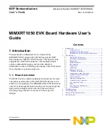
J24
J25
D8/CLKO/ICP1
NC
D9/OC1A/PWM
IOREF
D10/SPI_CS
RESET
D11/OC2A/PWM/SPI_MOSI 3.3V
D12/SPI_MISO
5V
D13/SPI_CLK
GND
GND
GND
AREF
VIN
D14/I2C_SDA
D15/I2C_SCL
2.14. Camera Module Connector
One parallel CSI (Camera Sensor Interface) is supported by the i.MX RT1050. There is a Camera
Module Connector (J35) on the MIMXRT1050 EVK Board. The CA031C based on OV7725 can be
used directly.
2.15. User Interface Switch
There are four user interface switches on the MIMXRT1050 EVK Board. Their functionality is as
below.
2.15.1. Power Switch
SW1 is a slide switch to control the power of the MIMXRT1050 EVK Board when the power supply is
from J2. The function of this switch is listed below:
•
Sliding the switch to the ON position connects the 5V power supply to the Evaluation board
main power system.
•
Sliding the switch to OFF position immediately removes all power from the board.
2.15.2. ON/OFF Button
SW2 is the ON/OFF button for MIMXRT1050 EVK Board. A short pressing in OFF mode causes the
internal power management state machine to change state to ON. In ON mode, a short pressing