Nvis 5586A
Nvis Technologies Pvt. Ltd.
50
When the LCD is controlled by the CPU, only the instruction register (IR) and the data
register (DR) can be read directly by the CPU. The commands from outside the modular can
decide the internal operation of LCD. These commands include the register selection (RS)
signals, read/write (R/W) signals, and data buffering signals (DB0-DB6).
Table 5 lists all the useful commands in the LCD modular and the execution time, these
commands are divided into the following group:
1.
Commands of set LCD module
2.
Commands of internal set address RAM
3.
Commands of data transfer in or out from the internal RAM
4.
Other commands
When the LCD modular is executing a command it will reject other commands. Except the
―busy flag/read address counter, the internal counting period of busy flag is set to as ―1‖. If
the CPU wants to send in other commands it will have to check the busy flag first, until it is
cleared to ―0‖ before it send in. The explanation is as followed:
Display Clear command:
This command will put the display data into a empty space‖ code (20H), address counter will
be cleared to 0. When executing this command, display OFF, the cursor or the character
blinking function will be moved to the most left side if it is in the set condition.
Display/Cursor Home:
The address counter will be cleared to 0, content of D.D. RAM will not be influenced; but if
the cursor or the character blinking function is in the set condition, it will be moved to the
most left side position.
Entry Mode Set:
I/D bit = ―1‖, ―1‖ is added in the address counter after each time it read/write a display data
RAM character code, so that the cursor or the character blinking function will move one
place to the left and vice-versa when I/D=0. The read/write (R/W) character generator also
has the same function.
S bit = 1, but each time it read/write a display data RAM code, it will move to the display
direction and move one space to the left (I/D=0) or one space to the right (I/D=1). When S=0,
the display will not move.
When data enters the character generator RAM, the display will not move.
Display ON/OFF:
D:
D=1
-
Display ON
D=0
-
Display OFF
C:
C=1
-
Cursor display on the display address of the display counter
C=0
-
Cursor does not display
Summary of Contents for 5586A
Page 2: ...Nvis 5586A Nvis Technologies Pvt Ltd 2...
Page 23: ...Nvis 5586A Nvis Technologies Pvt Ltd 23 Memory Read Timing in Maximum Mode...
Page 30: ...Nvis 5586A Nvis Technologies Pvt Ltd 30...
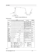
Page 48: ...Nvis 5586A Nvis Technologies Pvt Ltd 48 Diagram of module RESET power Instruction Set Note...

