Nvis 5586A
Nvis Technologies Pvt. Ltd.
14
the memory or I/O subsystem to signal the 8086 when they are ready to permit the data
transfer to be completed.
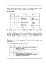
Interrupt signals:
The key interrupt interface signals are interrupt request (INTR) and
interrupt acknowledge (INTA). INTR is an input to the 8086 that can be used by an external
device to signal that it needs to be serviced. Logic 1 at INTR represents an active interrupt
request. When an interrupt request has been recognized by the 8086, it indicates this fact to
external circuit with pulse to logic 0 at the INTA output. The TEST input is also related to
the external interrupt interface. Execution of a WAIT instruction causes the 8086 to check
the logic level at the TEST input. If the logic 1 is found, the MPU suspend operation and
goes into the idle state. The 8086 no longer executes instructions; instead it repeatedly checks
the logic level of the TEST input waiting for its transition back to logic 0. As TEST switches
to 0, execution resume with the next instruction in the program. This feature can be used to
synchronize the operation of the 8086 to an event in external hardware. There are two more
inputs in the interrupt interface: the non-maskable interrupt NMI and the reset interrupt
RESET. On the 0-to-1 transition of NMI control is passed to a non-maskable interrupt
service routine. The RESET input is used to provide a hardware reset for the 8086. Switching
RESET to logic 0 initializes the internal register of the 8086 and initiates a reset service
routine.
DMA Interface signals:
The direct memory access DMA interface of the 8086 minimum
mode consist of the HOLD and HLDA signals. When an external device wants to take
control of the system bus, it signals to the 8086 by switching HOLD to the logic 1 level. At
the completion of the current bus cycle, the 8086 enters the hold state. In the hold state,
signal lines AD0 through AD15, A16/S3 through A19/S6, BHE, M/IO*, DT/R*, RD, WR,
DEN and INTR are all in the high Z state. The 8086 signals external device that it is in this
state by switching its HLDA output to logic 1 level.
Maximum Mode Interface:
When the 8086 is set for the maximum-mode configuration; it
provides signals for implementing a multiprocessor / coprocessor system environment. By
multiprocessor environment we mean that one microprocessor exists in the system and that
each processor is executing its own program. Usually in this type of system environment,
there are some system resources that are common to all processors. They are called as
global
resources
. There are also other resources that are assigned to specific processors. These are
known as
local
or
private resources
.
Coprocessor also means that there is a second processor in the system. In this, both
processors does not access the bus at the same time. One passes the control of the system bus
to the other and then may suspend its operation. In the maximum-mode 8086 system,
facilities are provided for implementing allocation of global resources and passing bus
control to other microprocessor or coprocessor.
Summary of Contents for 5586A
Page 2: ...Nvis 5586A Nvis Technologies Pvt Ltd 2...
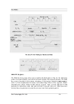
Page 23: ...Nvis 5586A Nvis Technologies Pvt Ltd 23 Memory Read Timing in Maximum Mode...
Page 30: ...Nvis 5586A Nvis Technologies Pvt Ltd 30...
Page 48: ...Nvis 5586A Nvis Technologies Pvt Ltd 48 Diagram of module RESET power Instruction Set Note...

