


NVIDIA Jetson TX2/TX2i OEM Product Design Guide
JETSON TX2/TX2i OEM PRODUCT | DESIGN GUIDE | 20180618
84
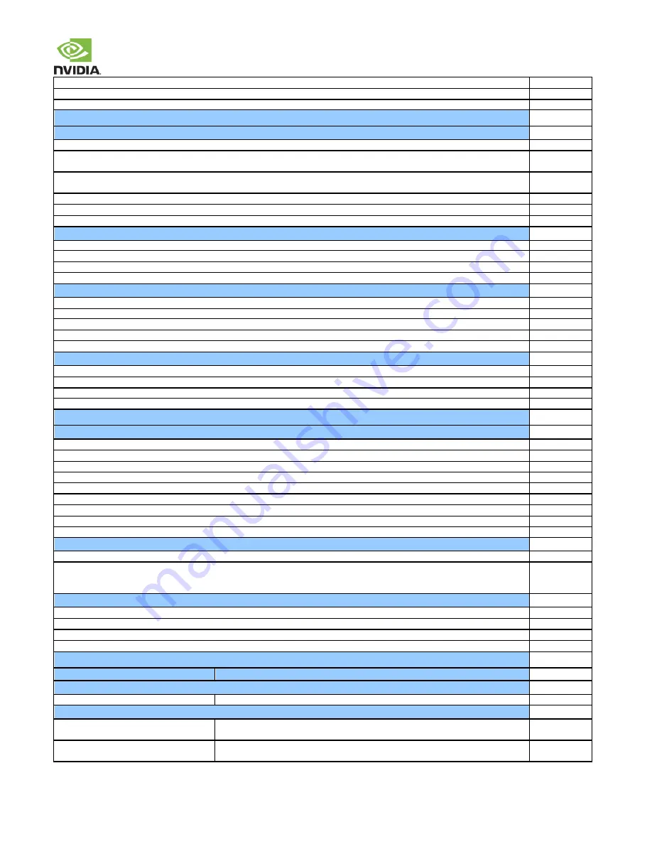
GPIO9_AUD_INT
Connect to interrupt pin of Audio Codec.
AO_DMIC_IN_CLK/DAT
connect to CLK/DAT pins of digital mic
DSPK_OUT_CLK/DAT
connect to CLK/DAT pins of digital speaker driver
I2C/SPI/UART
I2C
I2C devices on same I2C interface do not have address conflicts (comparisons are done 7-bit to 7-bit format or 8-bit to 8-bit format)
I2C_CAM, I2C_GP0, I2C_GP2, I2C_GP3 & I2C_PM
(See Signal Terminations). Additional external pull-ups are not added unless stronger
pull-up than on module required. Devices on bus are 1.8V or level shifter is used.
I2C_GP1
(See Signal Terminations). Additional external pull-ups are not added unless stronger pull-up than on module required &
devices on bus are 3.3V or level shifter is used.
Pull-up resistors are provided on the non-module side of any level shifters.
Pull-up resistor values based on frequency/load (check I2C Spec)
I2C_CAM_CK/DAT, I2C_GP[3:0]_CK/DAT & I2C_PM_CK/DAT
connect to SCL/SDA pins of devices
SPI
SPI[2:0]_CLK
connected to Peripheral CLK pin(s)
SPI[2:0]_MOSI
connected to Slave Peripheral MOSI pin(s)
SPI[2:0]_MISO
connected to Slave Peripheral MISO pin(s)
SPI2_CS[1:0]#
/
SPI[1:0]_CS0#
connected one CS# pin per SPI IF to each Slave Peripheral CS pin on the interface
CAN
CAN[1:0]_TX
connected to input data (RX) pins of respective CAN device
CAN[1:0]_RX
connected to output data (TX) pin of respective CAN device
CAN1_STBY
connected to Standby pin of respective CAN device
CAN[1:0]_ERR
connected to Error pin of respective CAN device
CAN_WAKE
connected to Wake pin of CAN devices
UART
UARTx_TX
connects to Peripheral RX pin of device
UARTx_RX
connects to Peripheral TX pin of device
UARTx_CTS
# connects to Peripheral RTS# pin of device
UARTx_RTS#
connects to Peripheral CTS# pin of device
Miscellaneous
JTAG
JTAG_TMS
Connect to
TMS
pin of connector
JTAG_TCK
Connect to
TCK
pin of connector (See Signal Terminations).
JTAG_TDO
Connect to
TDO
pin of connector
JTAG_TDI
Connect to
TDI
pin of connector
JTAG_RTCLK
Connect to
RTCK
pin of connector
JTAG_GP0 (JTAG_TRST#):
Connect to
TRST
pin of connector
JTAG_GP1 (NVJTAG_SEL):
For Boundary Scan test mode,
NVJTAG_SEL
is connected to
VDD_1V8
. (See Signal Terminations).
JTAG_GP1 (NVJTAG_SEL):
For normal operation,
NVJTAG_SEL
is pullled down. (See Signal Terminations).
Strapping
FORCE_RECOV#:
To enter Forced Recovery mode, pin is connected to
GND
when system is powered on.
All other module pins associated with strapping on Tegra X2:
Ensure any devices connected to module pins associated with Tegra X2
straps do not affect the level of the straps at power-on. Module pins affected are: SLEEP#, UART1_TX, UART0_RTS, RSVD-D8
(UART7_TX)
Pin Selection
Pinmux completed including GPIO usage (direction, initial state, Ext. PU/PD resistors, Deep Sleep state).
SFIO usage matches reference platform where possible.
Each SFIO function assigned to only one pin, even if function selected in Pinmux registers is not used or pin used as GPIO
GPIO usage matches reference platform where possible.
Unused SFIO (Special Function I/O) Interface Pins
Ball Name
Termination
USB 2.0
USB[2:1]
+/
–
Leave NC any unused pins
*USB 3.0 / PCIe
PEX_[2:0]_TX
+/
–
, USB_SS[1:0]_TX
+/
–
,
PEX_RFU_TX
+/
–
Leave NC any unused TX lines
PEX_[2:0]_RX
+/
–
, USB_SS[1:0]_RX
+/
–
,
PEX_RFU_RX
+/
–
Connect to
GND
any unused RX lines


