Auxiliary handle
The standard auxiliary handle is attached to the front collar of the drill.
It should always be used to ensure operating safety.
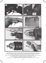
Depth stop (Pic. 4)
The drill is supplied with a depth stop used for drilling holes to a
required depth. Depress the spring loaded locking button located on
the side of the auxiliary handle (Pic.4) and insert the depth stop.
Measure back from the drill tip and move the depth stop back to the
required measured depth. The end of the depth stop will come into
contact with the work surface when the required depth of hole is
reached.
Tip for drilling tiles
Place a piece of masking tape onto the tile in the approximate position
for the hole. Mark the position of the hole onto the masking tape this will
prevent the drill from skidding across the tile when the drill is started.
Set the selector switch to the drill symbol and slowly drill through the
tile. When the tile has been fully drilled through change the selector
switch to the hammer symbol and continuing with hammer drilling.
Work piece clamping
To prevent the drill bit from spinning the work piece if the drill bit
becomes jammed in the hole being drilled, it is recommended that
a drill vice or other suitable clamp is used to secure the work piece
during the drilling operation.
Care and maintenance
This power tool normally requires no maintenance; from time to time
the ventilation slots on the motor casing should be cleaned out.
If the unit should become defective, repair should be performed by an
authorized service agent for electric tools.
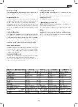
Fitting the side handle
To fit the side handle, unscrew the andle fully. Remove the bolt from
the clamping ring.
Pull open the clamping ring, untill it will pass over the chuck and locate
on to the body of the drill.
Re-fit the bolt and re-attach the side handle.
The bit-holder grip (Pic. 6)
NHD500 - NHD710:
The grip is pre-engineered to contain the bits of
the drill and the screwdriver inserts.
The kit also includes a pressure plug to close the bottom of the
handle.
Warning
Before opening the plug, remember to hold the grip so that it is facing
UP (Pic. 6) so that the bits it contains do not drop out with possible
damage to these or injuries to persons.
TECHNICAL SPECIFICATIONS
NHD500
NHD710
NHD860
NHD1050
Voltage
230-240 V ~ 50 Hz 230-240 V ~ 50 Hz 230-240 V ~ 50 Hz 230 V ~ 50 Hz
Rated Power
500 W
710 W
860 W
1050 W
Variable speed
0-2800 min
-1
0-3000 min
-1
0-2900 min
-1
0-3000 min
-1
Chuck size
13 mm
13 mm
13 mm
13 mm
Drill capacity:
Wood
20 mm
26 mm
25 mm
32 mm
Metal
10 mm
10 mm
13 mm
13 mm
Masonry
13 mm
13 mm
16 mm
16 mm
Sound Pressure Level
LPA 90.4 dB(A)
LPA 95,0 dB(A)
LPA 85,0 dB(A)
LPA 97 dB(A)
Sound Power Level
LWA 101.4 dB(A)
LWA 106,0 dB(A)
LWA 113,0 dB(A)
LWA 108 dB(A)
Vibration Level
metal:
masonry:
2,60
m/s
2
K
ID
:1,5 m/s
2
13,34 m/s
2
K
ID
:1,5 m/s
2
5,1 m/s
2
K
ID
:1,5 m/s
2
10,0
m/s
2
K
ID
:1,5 m/s
2
3,832 m/s
2
K
ID
:1,5 m/s
2
11,499 m/s
2
K
ID
:1,5 m/s
2
18.534
m/s
2
K
ID
:1.5 m/s
2
Weight
2.0 kg
1.94 kg
3.0 kg
2.4 kg
15
GB
Summary of Contents for NHD1050
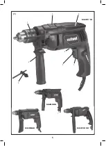
Page 5: ...5 1 8 2 3 4 5 7 1 9 6 NHD710 NHD1050 NHD860 NHD500 ...
Page 100: ...100 ...
Page 101: ...101 ...
Page 102: ...102 ...
Page 103: ...103 ...


