9
nuaire.co.uk
029 2085 8400
13. 03. 19. Document Number 671188
Installation and Maintenance
Ecosmart Boxer Air Handling Units
4.1 Connections
4.1.1 Mains Connections
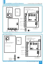
Mains cables should be suitably sized and terminated at terminals
shown on the appropriate diagram.
Where units form part of a system it will be necessary to install
and connect mains wiring between controls and devices such as
heat exchangers and motorised dampers - refer to the relevant
section of this document.
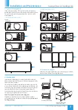
Where units are supplied in modular sections, sizes 3 to 7, it will
also be necessary to install and connect mains wiring between
sensors and actuators. Extension of the cable looms may be
required.
4.1.2 Control Connections
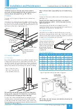
Net - the 4 IDC plug-in connectors are
provided for the connection of compatible
sensors, manual controls and for linking the
fans together under a common control.
If more than 4 connections are required, the
junction box (product code ES-JB) should be
used (see data cable installation).
Where units are supplied in modular sections, sizes 3 to 7, or as part
of a system it will also be necessary to install data cable (supplied)
between Ecosmart controls and from Ecosmart sensors and heat
exchanger etc.
4.1.3 Switched Live (SL) Terminal
A signal of 100 - 230V AC will
activate the fan from either its off
state or trickle state (see setting to
work-trickle switch). When the SL
is disconnected the fan will
over-run (see setting to
work-timer adjustment).
Do not take this signal from an
isolating transformer.
4.1.4 Damper Connections
4.1.6 Data Cable Installation
A 4-core SELV data cable is used to connect devices. Do not run data
cable in the same conduit as the mains cables and ensure there is
a 50mm separation between the data cable and other cables. The
maximum cable run between any two devices is 300m when it is
installed in accordance with the instructions.
Please note that the total data cable length used in any system
must be less than 1000m. Keep the number of cable joints to a
minimum to ensure the best data transmission efficiency between
devices.
4.1.7 Maximum Number of Devices
The maximum number of devices (including fans) that can be
connected together via the cable is 32, irrespective of their functions.
4.1.8 Other Low Voltage Cables
Follow the basic principle
(as Data cable installation)
. Keep the cable
run as short as possible and less than 50 metres.
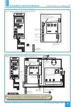
4.1.9 BMS Input Signals
The BMS connection is made with a plug-in connector
via the socket (Figure 22). To ensure the connection
is made only by suitably qualified and authorised
personnel the plug is not supplied.
It is available from R S Components, Part No. 403-875
or Farnell, Part No. 963-021.
4.1.5 Volt Free Relay Contacts
Note that the volt free contacts are not
fused. If these are used to power any external
equipment, the installer must provide
adequate fusing or other protections.
These contacts are rated at 5A resistive, 0.5A
inductive.
Run Connections
= Contacts closed when fan is running.
Fault Connections: No fault
= Contacts closed.
Fault
= Contacts open.
Heat Demand
= Contacts closed when heating selected.
Cooling Demand
= Contacts closed when cooling selected.
Do not use this contact to switch compressors directly.
Frost Alarm
- Contacts closed when air off temperature is 4°C or
below. Fan shuts down, valve opens and the heat demand contacts
activated.
DX1
- contacts close when stage 1 of DX coil selected.
DX2
- contacts close when stage 2 of DX coil selected.
OP
- 230V 50Hz 1A max supply to open the damper
CL
- 230V 50Hz 1A max supply to close the damper
N
- Neutral supply to damper
RET
- 230V ac return signal from the damper limit switch indicates the
damper has reached its operating position. If the return signal is not
present, the fan will wait for 1 minute before starting.
Note: If a damper is not fitted, connect a link wire from OP to RET. This
will cancel the delay.
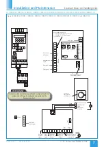
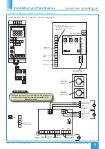
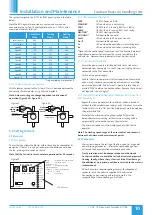
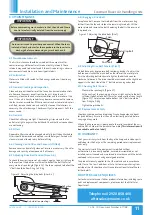
Figure 16. ‘Net’ connection
for Ecosmart devices.
Figure 20.
Figure 22.
Figure 21.
Figure 17.
Figure 18. Drive Open/
Spring Close.
Figure 19. Drive Open/
Drive Close.
SL
L
E
N
Remove link if switched live signal, an
enabler or BMS signal is connected
Mains connection
230V 50Hz 1PH
OP
S4
S6
230V
motor
230V
motor
A fan starting delay
of 1 minute is
imposed to enable
the damper to
open.
To override the
delay fit a link here.
A fan starting delay
of 1 minute is
imposed to enable
the damper to
open.
To override the
delay fit a link here.
All wiring is 1PH 230V 50Hz
All wiring is 1PH 230V 50Hz
White
Brown
Blue
2
1
CL
N
RET
OP
CL
N
RET
RUN
Run signal
Fault signal
FAULT
Cooling
Demand
Signal
Frost
Alarm
Signal
Signal for
DX1 coil
if fitted
Signal for
DX2 coil
if fitted
Connect to inlet
sensor after unit
is assembled
Outlet
sensor
Inlet
Sensor
BMS
0-10V
10V
IMPORTANT
Reversal of the BMS connection will damage the control.


