11
nuaire.co.uk
029 2085 8400
13. 03. 19. Document Number 671188
Installation and Maintenance
Ecosmart Boxer Air Handling Units
6.0 MAINTENANCE
6.1 Maintenance Intervals
The first maintenance should be carried out three months after
commissioning and thereafter at twelve monthly intervals. These
intervals may need to be shortened if the unit is operating in adverse
environmental conditions, or in heavily polluted air.
6.2 Lubrication
Motors are fitted with sealed for life bearings and do not require any
lubrication.
6.3 General Cleaning and Inspection
Clean and inspect the exterior of the fan unit and associated controls
etc. Remove the access panel from the fan unit. Inspect and, if
necessary, clean the fan and motor assemblies and the interior of the
case. If the unit is heavily soiled it may be more convenient to remove
the fan / motor assemblies. If Nuaire controls and or remote indicators
are fitted, remove the covers and carefully clean out the interiors as
necessary. Check for damage. Check security of components. Refit the
access covers.
6.4 General
Check that all fixings are tight. Check sealing strips around the fan
outlets are tight up against the bulkhead. Check that duct connections
are not leaking.
6.5 Filters
Disposable filters should be changed when fully dust laden. Washable
filters should be removed and washed in mild detergent, flushed with
clean water and allowed to dry before refitting.
6.6 Cleaning Control Box and Sensors (if fitted)
Remove covers and carefully clean out interiors as necessary. Check for
damage and security of components. Refit covers.
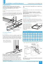
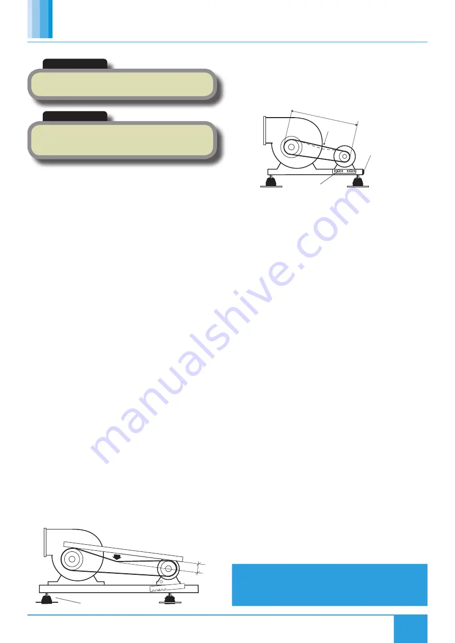
6.7 Adjusting Drive Belt Tension (Sizes 3-6)
To check the correct tension of a drive belt, apply a force at right angles
to the centre of the belt span sufficient to deflect the belt 16mm for
every metre of span length (Figure 26). The force required to deflect the
‘V’ belt should be from 0.5kg to 0.8kg.
6.8 Changing a Drive Belt
To replace a belt, remove the two bolts from the motor mounting
furthest from the fan and slacken the remaining two bolts. Lift the
motor plate and remove the belt. Replacing the belt is the reverse of
this procedure.
6.9 Adjusting Drive Belt Tension (Size 7)
All belt drive units incorporate belt tensioning devices. To adjust the
belt tension, slacken the pinch bolt on the sides of the motor plate.
Turn the adjusting bolt clockwise to tighten the belt and counter
clockwise to loosen it. The drive should be tensioned until a slight bow
appears in the slack side of the ‘V’ belt when running under load.
6.10 Checking Belt Tension
•
Measure the span length (Figure 27).
•
At the centre of the span, apply a force at right angles to the belt
sufficient to deflect one belt 16mm for every metre of span length
(Figure 27). The force required to deflect the ‘V’ belt should be
from 0.5kg to 0.8kg.
•
Tighten the pinch bolts.
6.11 Replacement of Parts
Should any component need replacing Nuaire keep extensive stocks
for quick delivery. Ensure that the unit is electrically isolated, before
carrying out any work.
When ordering spare parts, please quote the serial number of the unit
and the ARC number of the purchase if possible
(This information will
be available on the fan label).
7.0 WARRANTY
The 5 year warranty starts from the day of delivery and includes parts
and labour for the first year. The remaining period covers replacement
parts only.
This warranty is void if the equipment is modified without
authorisation, is incorrectly applied, misused, disassembled, or not
installed, commissioned and maintained in accordance with the details
contained in this manual and general good practice.
The product warranty applies to the UK mainland and in accordance
with Clause 14 of our Conditions of Sale. Customers purchasing from
outside of the UK should contact Nuaire International Sales office for
further details
8.0 AFTER SALES ENQUIRIES
For technical assistance or further product information, including spare
parts and replacement components, please contact the After Sales
Department.
IMPORTANT
Before commencing work, make sure that the unit and Nuaire
control are electrically isolated from the mains supply.
IMPORTANT
An Inverter is used to provide speed control. When the fan is
isolated, allow 5 minutes for the capacitors in the inverter to
discharge before commencing any work on the unit.
Anti-vibration moutings
Deflection
Figure 26. Adjusting the drive belts (Sizes 3-6).
Span
Force
Adusting Bolt
Pinch Bolt
Figure 27. Adjusting the drive belts (Size 7).
Telephone 02920 858 400


