background image

8

nuaire.co.uk 

029 2085 8400

13. 03. 19. Document Number  671188

Installation and Maintenance

Ecosmart Boxer Air Handling Units

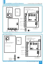
Connections 

to Damper

N

L

SL

DP

CL

N

RET

Remove this link wire if: 

NET connections for 

ECOSMART devices

1. a switched live signal is connected.

2. A ES-PIR, ES-TC or BMS signal

is connected.

Max     SL run on

Min         

Trickle

Test

1

0        

Pwr
Standby
Fan 1
Fan 2
Heating
Cooling
Fault
Frost
Tx
Rx

Ecosmart

Heat demand  

signal

Earth

Run signal

Fault signal

DAMPER 

FAULT     RUN

HEAT DEMAND

L3
L2

L1

N

E

400V 50Hz  

3ph +N mains

5

3          

6

  1         

  2          4         

(U)

(V)     (W)

E

L3   

L2 

L1  

(U)

(V)    (W)

L3

L2

L1

15

14   

12  13  

9

8   

7   

6    

5   

11 

10   

15

13  14   

12  

CONTACTER

A1

A2

ON  OFF

AUTO 

HEATER/COOL

Cooling  

signal

demand  

Frost 

signal

alarm  

DX1 coil 

Signal for  

if fitted

DX2 coil 

Signal for  

if fitted

Connect to inlet  

sensor after unit  

is assembled

Outlet  

sensor

sensor

Inlet  

3
2

1

GREEN
BROWN
WHITE

Connect to LPHW  

actuator motor  

SM24 

position A

motor set at  

25

30

25

Set outlet air  

temperature  

coil 

ofCW cooling  

25

30

25

Set outlet air  

of LPHW coil 

temperature  

3
2

1

GREEN
BROWN
WHITE

Connect to CW coil  

SM24 

actuator motor  

position A

motor set at  

0V

0-10V

BMS signal

A

A

A

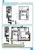
Figure 15. ESBHS3-LC, ESBHS4-LC, ESBHS5-LC, ESBHS6-LC and ESBHS7-LC.

IMPORTANT

Actuator and sensors (A) are positioned in adjacent modular 

sections and will require wiring and connection to the  

Ecosmart control.

4.2.8 ESBHS3-LC, ESBHS4-LC, ESBHS5-LC, ESBHS6-LC and ESBHS7-LC

Summary of Contents for ESBH Series

Page 1: ...t Terminals Weathering Roof Sensors User controls For systems which include supply fans with heating and or cooling coils other than where the BMS has control the appropriate user control is required...

Page 2: ...etised Forklift Slings via spreaders fitted to unit with base frame Figure 2 Figure 3 Figure 4 2 0 HANDLING Upon receipt of the equipment an inspection should be made and before commencement of liftin...

Page 3: ...equired install on a secure and level surface use the base frame and the weather roof tailored for each system Connect ducting inlet or extract cowls as appropriate 3 2 5 Wet Pipe Connections 3 2 Asse...

Page 4: ...erse effect on lighting etc There are no inrush starting currents quoted because the Ecosmart control incorporates a soft starting speed control feature The inverters are pre set to match the fan heat...

Page 5: ...itted DX2 coil Signal for if fitted 25 30 2 5 Set air off of LPHW coil temperature 0V 0 10V BMS signal Connections to Damper N L SL DP CL N RET Remove this link wire if NET connections for ECOSMART de...

Page 6: ...n 2 Heating Cooling Fault Frost Tx Rx Ecosmart signal Heat demand Run signal Fault signal DAMPER FAULT RUN HEAT DEMAND L3 L2 L1 N E 400V 50Hz 3ph N mains supply for fan 5 6 3 1 4 2 U V W E L1 L2 L3 U...

Page 7: ...1 15 13 14 12 9 7 5 8 6 10 11 15 12 14 13 CONTACTER A1 A2 ON OFF AUTO HEATER COOL Cooling signal demand Frost alarm signal DX1 coil Signal for if fitted Signal for DX2 coil if fitted 25 3 0 25 Set air...

Page 8: ...15 13 14 12 CONTACTER A1 A2 ON OFF AUTO HEATER COOL Cooling signal demand Frost signal alarm DX1 coil Signal for if fitted DX2 coil Signal for if fitted Connect to inlet sensor after unit is assemble...

Page 9: ...e as Data cable installation Keep the cable run as short as possible and less than 50 metres 4 1 9 BMS Input Signals The BMS connection is made with a plug in connector via the socket Figure 22 To ens...

Page 10: ...hen a fault is present on unit Frost Not applicable see note Tx LED on when the controller is transmitting data Rx LED on when the controller is receiving data Note that the control panel is common to...

Page 11: ...lt Tension Size 7 All belt drive units incorporate belt tensioning devices To adjust the belt tension slacken the pinch bolt on the sides of the motor plate Turn the adjusting bolt clockwise to tighte...

Page 12: ...s of contaminants 4 0 OPERATIONAL LIMITS 4 1 It is important that the specified operational limits for the equipment are adhered to e g operational air temperature air borne contaminants and unit orie...

Reviews: