3
nuaire.co.uk
029 2085 8400
13. 03. 19. Document Number 671188
Installation and Maintenance
Ecosmart Boxer Air Handling Units
3.0 INSTALLATION
Installation must be carried out by competent personnel in
accordance with the appropriate authority and conforming to all
statutory and governing regulations e.g. IEE, CIBSE etc.
3.1 Erection
Unit sizes 1 and 2 are generally single section units and require no
assembly.
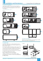
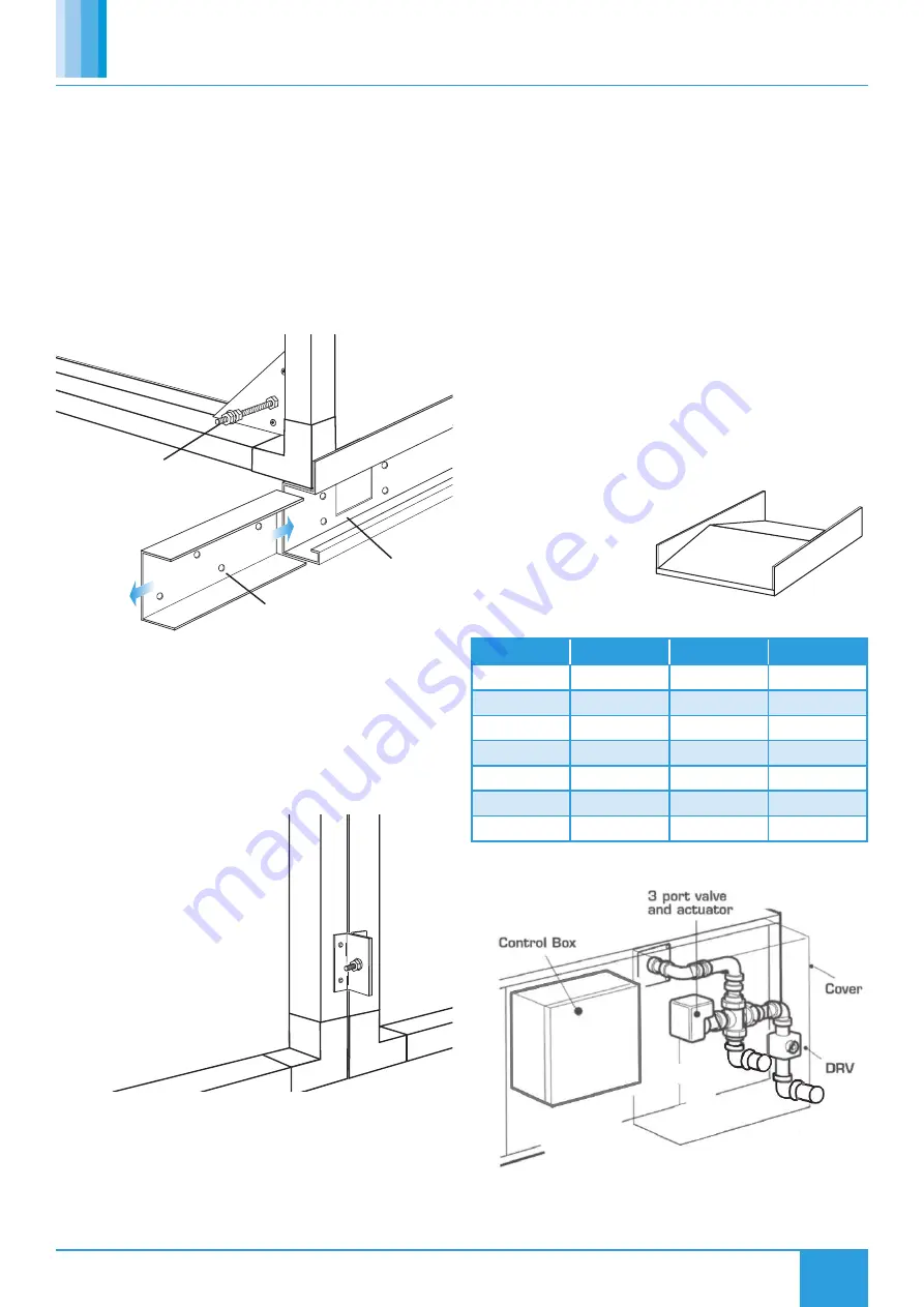
Unit sizes 3 to 7 are multi-section units supplied on a base frame. The
units and base frame will require bolting together using matched drilled
flanges and the nuts and bolts provided. In addition fish-plates must be
used to join two base frames together (Figure 5).
Note: It is the assembler’s responsibility to seal all modular facing
joints.
3.2.2 Electrical
On sizes 3 to 7 the various modular sections are delivered separately for
assembly on site.
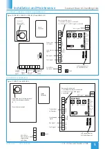
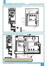
Ensure that all inter-connecting wiring looms are connected
between the adjoining modules - refer to the appropriate wiring
diagram in section 5.
When selecting the unit position, ensure adequate access for
connection of external services, commissioning, future inspection and
maintenance and the removal of component parts.
3.2.3 Indoor Installation
The standard fan is suitable for installation indoors only, away from
heat sources, steam generation or water spray. Site the fan on a secure
and level surface, using the base frame provided, suspend on a platform
or support rails, alternatively hang using drop rods.
3.2.4 External Installation
Where an external installation is
required, install on a secure and
level surface, use the base frame
and the weather roof tailored
for each system. Connect
ducting, inlet or extract cowls
as appropriate.
3.2.5 Wet Pipe Connections
3.2 Assembly of Equipment
3.2.1 Mechanical
Ensure all components and sections are available to complete the work.
The flanges of facing sections must be offered one to the other, and
secured via the studs and nuts provided. Access to each securing point
is by removal of the access doors on each section. Each joint must be
appropriately sealed to ensure weathering and to prevent air leakage.
Where cooling coils and heat exchangers are in use condensate
drainage points are provided. It is the installers’ responsibility to
ensure connection to the appropriate trap and drainage.
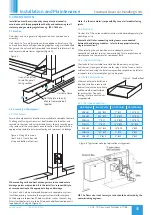
On sizes 1 and 2, where motorised dampers are coupled to a system,
it will be necessary to remove the spigot section inlet/discharge to
fix the damper into position. Where ancillaries such as silencers, bag
filters, frost heaters etc. are to be fitted, each additional component is
supplied with a fixing kit (Figure 6).
NB: The flow valve is not factory set and should be adjusted by the
commissioning engineer.
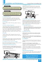
Slot fishplate into ends
of base frames and bolt
together.
Unit base frame.
Use nuts and studs
to join flanges of
facing sections.
Figure 5.
Figure 7. Weather Roof
Figure 6. Fixing kit in use on
sizes 1 and 2. One to be used
at top and bottom of sections.
Figure 8. Typical wet coil pipe termination arrangement.
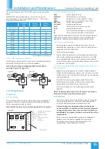
Unit Model
Frost Coils
CHW Coils
LPHW Coils
ESBHS1
0.75" BSP
1" BSP
1.25" BSP
ESBHS2
0.75" BSP
1.25" BSP
1.25" BSP
ESBHS3
1" BSP
1.25" BSP
1.25" BSP
ESBHS4
1" BSP
1.25" BSP
1.5" BSP
ESBHS5
1.25" BSP
1.5" BSP
2" BSP
ESBHS6
1.25" BSP
2" BSP
2" BSP
ESBHS7
1.5" BSP
2" BSP
2" BSP


