Pre-firing Checks and Dry Run
With the oil and power switched off, carry out the following checks:
Check the nozzle size and position relative to the diffuser plate. (The burner head dimensional details
are given in the
appendix
of this handbook)
.
Check that the electrode positions and HT leads are correct.
Check all the motor overload settings.
If the appliance is a boiler, check that the water level is correct, the controlling valves are open and that
the water pumps are in working order.
If a flue damper is fitted, check that it is correctly interlocked to the burner or fixed in the fully open
position.
Ensure that there is a good oil supply to the burner pump. Bleed one or two gallons from the flexible to
eliminate any pipe scale and air from the system.
Check that the oil supply is of the recommended temperature and pressure.
Bleed the burner pump manually by removing the right-hand ¼” BSP plug in the top of the pump until
air-free oil flows.
Switch on the electricity supply to the burner and check that the pump motor rotation is correct to the
direction arrows shown on the pump face.
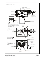
Modulating Burners
Remove the access lid on the modulating cam box unit.
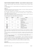
Switch on the burner at the control panel. The modulating unit cam shaft should now rotate to the high
flame setting, and the combustion air motor will start the air pre-purge phase.
Allow the fan motor to run up to speed, switch off the burner and check the fan rotation (anti-clockwise
as viewed from the motor side) as the fan slows down.
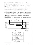
Remove and cover the photoelectric cell with a clean lint-free cloth, switch on the burner, and allow it
to run through to lockout. During this run check that the ignition spark is occurring, and note the spill
and line oil pressures at the moment of ignition. Reset the sequence control and repeat the run if
necessary to check these functions. If necessary, adjust the spill pressure to the correct figure according
to the nozzle specification and the line pressure at the burner pump to 27.8 bar (400 psi).
High/Low Burners
Check that the total nozzle size is correct for the particular application. The normal operating pressure
of the burner is 20 atm (20.7 bar : 300 lbf/in
2
). To obtain nozzle throughput in Imperial gal/h multiply
marking by 1.44. To obtain nozzle throughput in litres per hour multiply by 6.55, and for kg/h multiply
by 6.2.
Check ignition electrodes and leads and the position of the nozzles relative to the face of the diffuser.
When replacing the inner assembly ensure that the ‘O’ rings are correctly in position between the union
blocks.
The works setting of the air regulator is 6mm (¼”) open for low flame and 19mm (¾”) for high flame.
The sequencing microswitch is set to bring in high flame oil after the air regulator has moved from 6mm
(¼”) away from the low position. The air regulator is adjusted by means of set pins acting on a stop
carried on the moving member of the regulator.
Access to the set pins and the sequencing microswitch is obtained by removal of the plate at the top of
the silencer.
Check that all controls and flue dampers are correctly set.
Turn switch on control panel to ‘low flame hold’ and ensure that there is water in the boiler.
Remove and cover the photoelectric cell with a clean lint-free cloth, switch on the burner, and allow it
to run through to lockout. during this run check that the ignition spark is occurring, and note the pump
pressure.
MOL 3400-4100 Issue 2 10/08
Page 15
Summary of Contents for MOL 3400-410
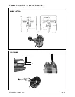
Page 18: ...MOL 3400 4100 Issue 2 10 08 Page 17 MODULATING UNIT Cams shown in the Low Flame Position...
Page 35: ...NOTES...
Page 36: ...NOTES...


