INSTALLATION
General
Ensure that the appliance is suitable for the heat input of the burner. If there is any doubt in this area,
reference shall be made to the appliance manufacturer. Detailed burner performance data are presented
in the
appendix
of this handbook.
Fitting to the Appliance
If the burner is to be fitted to a new appliance refer to the appliance manufacturers recommendations.
If the burner is to be fitted to an existing appliance a mounting flange must be provided as detailed in the
section of
Burner & Components Identification
. Ensure that the joint between the burner and the mounting
flange is sealed effectively using the gasket provided.
The flame tube should not extend beyond the inner face of the appliance combustion chamber unless the
appliance manufacturer specifies extensions, for example in the case of reverse flame boilers.
Connections
Once the burner is mounted to the appliance, open the hinged extension by removing the two nuts and
washers, connect the HT leads to the ignition electrodes and close and fasten the extension.
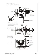
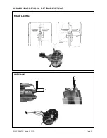
Connect the flexible oil pipes between the burner and the pumping unit by referring to the burner
component and pumping unit drawings on pages 4 & 13.
Connect the oil supply to the burner pumping unit with reference to the oil system diagrams and pumping
unit drawings on pages 10 & 19.
Electrical Power Connection
Connect a three-phase, 50 Hz electrical supply to the burner, observing all applicable Codes and
Standards. The electrical connections required are shown in the wiring diagram contained in the
instruction pack attached to the burner. These diagrams also show the auxiliary control connections,
which must be made.
If the burner is supplied as part of a packaged appliance/burner unit, refer to the appliance manufacturers
instructions.
New Wiring Colours
In accordance with the Requirements for electrical Installations BS 7671:2001 Amendment No.2 (the IEE
wiring regulations), wiring colour coding has been amended to Brown (L) and Blue (N) for single phase
power circuits, and Brown (L1), Black (L2), Grey (L3) and Blue (N)
in three-phase power circuits
from
1
st
June 2006.
Full details of the changes can be found in amendment No.2 9AMD 14905 to BS 7674:2001 – which is a
free download from the IEE website (www.iee.org/cablecolours). They are also within the new version of
BS 7671:2001 (Incorporating Amds 1 & 2) published on 31
st
March, this new version of the Wiring
Regulations can be identified by its brown cover.
MOL 3400-4100 Issue 2 10/08
Page 11
Summary of Contents for MOL 3400-410
Page 18: ...MOL 3400 4100 Issue 2 10 08 Page 17 MODULATING UNIT Cams shown in the Low Flame Position...
Page 35: ...NOTES...
Page 36: ...NOTES...


