N1050 Controller
NOVUS AUTOMATION
6/8
ACCESS PASSWORD
The protected levels, when accessed, request the user to provide the
Access Password
for granting permission to change the
configuration of the parameters on these levels.
The prompt
PASS
precedes the parameters on the protected levels.
If no password is entered, the parameters of the protected levels can
only be visualized.
The Access Password is defined by the user in the parameter
Password Change
(
PAS.C
), present in the Calibration Level.
The
factory default for the password code is 1111.
PROTECTION ACCESS PASSWORD
The protection system built into the controller blocks for 10 minutes
the access to protected parameters after 5 consecutive frustrated
attempts of guessing the correct password.
MASTER PASSWORD
The Master Password is intended for allowing the user to define a
new password in the event of it being forgotten. The Master
Password doesn’t grant access to all parameters, only to the
Password Change
parameter (
PASC
). After defining the new
password, the protected parameters may be accessed (and
modified) using this new password.
The master password is made up by the last three digits of the serial
number of the controller
added
to the number 9000.
As an example, for the equipment with serial number 07154321, the
master password is 9 3 2 1.
RAMP AND SOAK PROGRAMS
Characteristic that allows the elaboration of a behavior profile for the
process. Each program consists of a set of up to 4 segments, called
RAMPS AND SOAKS PROGRAM, defined by SP values and time
intervals.
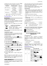
Up to 5 different ramp and soak programs can be created. The figure
below displays a profile model:
Fig. 03
- Example of a Ramp and Roak
Once the program is defined and executed, the controller
automatically generates the SP according to the program.
To execute a program with a number of segments smaller than 4
(four), simply program 0 (zero) for the next segment time to the last
desired segment.
The program tolerance function
P.toL
defines the maximum
deviation between PV and SP during program execution. If this
deviation is exceeded, the time count is interrupted until the deviation
is within the programmed tolerance (gives SP priority). If zero is set
in the tolerance, the controller executes the defined program without
considering any deviations between PV and SP (gives priority to
time).
Restore Program after Power Failure (Program restore)
Function that defines the behavior of the controller when it resumes
from a power failure in the midst of a program execution of ramps
and levels. The restore options are:
Prog
- Returns at the beginning of the program;
P.seg
- Returns the beginning of the segment;
t.seg
- Returns to the point of the previous program segment the
power failure;
off
- Returns with control disabled (
RUN
=
No)
.
The
t.seg
option has its performance related to the configuration
adopted by the parameter
P.toL
. Thus, it also has the following
functions:
1- With
P.toL
set to zero, the controller resumes the execution
of the program immediately after the energy return (from the
point and segment where it stopped), regardless of the
PV
value
at that time.
2- With
P.toL
non-zero, the controller waits until
PV
enters the
deviation range defined by the value of
P.toL
and then
resumes the program execution.
Link
of programs
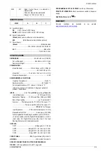
It is possible to create a large, more complex program with up to 20
segments connecting the 5 programs. Thus, at the end of the
execution of a program, the controller immediately starts executing
another program.
In the elaboration of a program it was defined in the screen
LP
whether or not there will be connection to another program.
In order for the controller to be able to run a certain program or
programs continuously, simply connect a program to itself or the last
program to the first one.
Fig. 04
– Link programs example
Event Alarm
The Event Alarm function allows you to program the triggering of
alarms in specific segments of a program.
For this function to operate, the alarms to be triggered must have their
function set to
rS
and are configured in parameters
PE1
to
PE4
.
Hold Program Function
This function stops program execution when the
key is pressed.
The
H.Prg
parameter of the Calibration Cycle enables the key
to perform this function. Pressing the
key for 3 seconds will
immediately program the program. A new press, also of 3 seconds,
resumes its execution.
DETERMINATION OF PID PARAMETERS
During the process of determining automatically the PID parameters,
the system is controlled in
ON/OFF
in the programmed Setpoint. The
auto-tuning process may take several minutes to be completed,
depending on the system. The steps for executing the PID auto-
tuning are:
•
Select the process Setpoint.
•
Enable auto-tuning at the parameter
Atun
, selecting
FAST
or
FULL
.
The option
FAST
performs the tuning in the minimum possible time,
while the option
FULL
gives priority to accuracy over the speed.
The sign TUNE remains lit during the whole tuning phase. The user
must wait for the tuning to be completed before using the controller.
During auto tuning period the controller will impose oscillations to the
process. PV will oscillate around the programmed set point and
controller output will switch on and off many times.

