background image


NOVUS AUTOMATION


2/57


1.


SAFETY ALERTS ...........................................................................................................................................................................................3


2.


INTRODUCTION .............................................................................................................................................................................................4


3.


DISPLAY AND NAVIGATION .........................................................................................................................................................................5


3.1


DISPLAY INFORMATION ...............................................................................................................................................................................5


3.2


OPERATION KEYS ........................................................................................................................................................................................6


3.3


NAVIGATION KEYS .......................................................................................................................................................................................6


4.


OPERATION AUTONOMY ...........................................................................................................................................................................10


5.


INPUT SIGNALS READING .........................................................................................................................................................................11


6.1


ANALOG INPUTS .........................................................................................................................................................................................11


6.1.1


MEASUREMENT AND INDICATION OF INPUT TYPES .............................................................................................................................12


6.2


DIGITAL INPUT ............................................................................................................................................................................................14


6.2.1


PULSE COUNT .............................................................................................................................................................................................14


6.2.2


EVENT LOG ..................................................................................................................................................................................................15


6.2.3


LOG CONTROL ............................................................................................................................................................................................15


6.


DATA LOGGING ...........................................................................................................................................................................................16


7.


DIGITAL OUTPUT ........................................................................................................................................................................................17


8.


ALARMS........................................................................................................................................................................................................18


9.


CONFIGURATION SOFTWARE...................................................................................................................................................................19


10.1


NXPERIENCE ...............................................................................................................................................................................................19


10.2


NXPERIENCE-BLE .......................................................................................................................................................................................19


10.3


CONFIGURING WITH NXPERIENCE / NXPERIENCE-BLE .......................................................................................................................19


10.3.1


GENERAL PARAMETERS ...........................................................................................................................................................................19


10.3.2


ANALOG CHANNELS PARAMETERS .........................................................................................................................................................20


10.3.3


DIGITAL CHANNEL PARAMETERS ............................................................................................................................................................21


10.3.4


CHANNELS GENERAL PARAMETERS.......................................................................................................................................................23


10.3.5


DATA LOGGING CONFIGURATION............................................................................................................................................................23


10.4


DIAGNOSTICS .............................................................................................................................................................................................25


10.4.1


LOGS ............................................................................................................................................................................................................25


10.4.2


CHANNELS ...................................................................................................................................................................................................26


10.4.3


MISCELLANEOUS ........................................................................................................................................................................................26


10.5


NXPERIENCE-BLE SPECIFIC FEATURES .................................................................................................................................................26


10.5.1


INSTALLING THE APPLICATION ................................................................................................................................................................26


10.5.2


APPLICATION OPERATION ........................................................................................................................................................................26


10.5.3


CONFIGURATION ........................................................................................................................................................................................29


10.5.3.1


STATUS ....................................................................................................................................................................................................... 29


10.5.3.2


CONFIGURATION ....................................................................................................................................................................................... 30


10.5.3.3


LOGS ........................................................................................................................................................................................................... 30


10.5.3.4


SETTINGS ................................................................................................................................................................................................... 39


10.5.3.5


MANAGER ................................................................................................................................................................................................... 39


10.6


MONITORING ...............................................................................................................................................................................................39


10.7


FILE MANAGER ...........................................................................................................................................................................................41


10.8


SETTINGS ....................................................................................................................................................................................................44


10.


INSTALLATION .............................................................................................................................................................................................46


MECHANICAL INSTALLATION ....................................................................................................................................................................46


11.1

11.1.1


DIMENSIONS ...............................................................................................................................................................................................47


ELECTRICAL INSTALLATION .....................................................................................................................................................................48


11.2


INSTALLATION RECOMMENDATIONS ......................................................................................................................................................48


11.2.1


SPECIAL CARE ............................................................................................................................................................................................48


11.2.2


ELECTRICAL CONNECTIONS ....................................................................................................................................................................48


11.2.3

11.


COMMUNICATION INTERFACES ...............................................................................................................................................................51


USB ...............................................................................................................................................................................................................51


12.1


BLUETOOTH ................................................................................................................................................................................................51


12.2

12.


TROUBLESHOOTING ..................................................................................................................................................................................53


13.


TECHNICAL SPECIFICATIONS ...................................................................................................................................................................54


13.1


SENSORS RANGE AND ACCURACY .........................................................................................................................................................55


14.


WARRANTY ..................................................................................................................................................................................................57


Summary of Contents for LogBox-BLE

Page 1: ...0 cm shall be maintained between the antenna and users and the transmitter module may not be co located with any other transmitter or antenna Canada This Class A digital apparatus complies with Canadi...

Page 2: ...AMETERS 21 10 3 4 CHANNELS GENERAL PARAMETERS 23 10 3 5 DATA LOGGING CONFIGURATION 23 10 4 DIAGNOSTICS 25 10 4 1 LOGS 25 10 4 2 CHANNELS 26 10 4 3 MISCELLANEOUS 26 10 5 NXPERIENCE BLE SPECIFIC FEATURE...

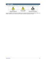
Page 3: ...alling and operating the device CAUTION OR DANGER Risk of electric shock ATTENTION Material sensitive to static charge Be sure to take precautions before handling All safety recommendations in this ma...

Page 4: ...ltage and external source voltage which can also record the values in the memory taking the place of any of the available measurement channels Its wide display allows you to view up to 3 variables sim...

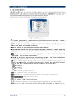
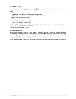
Page 5: ...day at a certain time it will only remain lit within the configured time Flashes at the time of a log turns off at the time of a log and restarts Lights up and stays on when you enter an alarm condit...

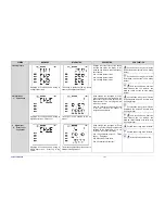
Page 6: ...of time For more information refer to chapter CONFIGURATION SOFTWARE If the buzzer is active any key pressed will mute it 3 3 NAVIGATION KEYS When navigating between screens a mnemonic is always displ...

Page 7: ...ed in the pulse count of the last record period for the digital channel If it is not configured this screen is not shown Uses the 3 display lines to display the flow in the user unit with the number o...

Page 8: ...Displayed for 2 seconds before moving to Date Time screen This screen is updated by the log interval and or by the display update range Displays the device s current date and time Line 1 Year Line 2 M...

Page 9: ...ses contrast maximum of 7 Key held down or long touch Decreases contrast minimum of 0 Both keys held down No action 7 Log Status Displayed for 2 seconds before moving to Log Status screen This screen...

Page 10: ...perating the device in these ranges consider that the 2 year expectation can be reduced considerably Some scenarios can greatly increase LogBox BLE consumption thus considerable reducing the battery s...

Page 11: ...ting in the Event Log mode it updates its respective information on the display to each event 6 1 ANALOG INPUTS LogBox BLE has three channels for reading analog signals The types of signals and sensor...

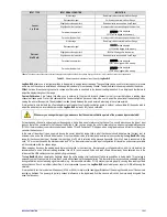
Page 12: ...d Slightly above the upper limit 22000 will be logged in the memory Slightly under the lower limit Read input value Far above the upper limit vvvv will be displayed 32767 will be logged in the memory...

Page 13: ...indication to a local standard since the LogBox BLE is already fully factory calibrated Whenever you change the input type make sure that the custom calibration points of the previous input are delet...

Page 14: ...pulses within a given range and logging it in the memory Thus at each log interval LogBox BLE captures the number of pulses within that interval and logs it in the memory zeroing the register to accum...

Page 15: ...ieces per minute Thus LogBox BLE will log in each log interval the number of pulses occurring within that period and every time the data is displayed it will turn those pulses into the number of piece...

Page 16: ...al Input When the Digital Input is triggered the logs are started In this case the Digital Input channel must have been set to Log Control To control the logs by Digital Input 4 modes are possible Sta...

Page 17: ...ic Switch mode it is necessary to set how long before each acquisition the digital output must be triggered Drive Time Set in seconds in the Auxiliary Electronic Switch mode how long before each acqui...

Page 18: ...el can be cleared by the user through the display screens or through NXperience or NXperience BLE For each enabled channel it is possible to enable a minimum alarm and a maximum alarm For each alarm i...

Page 19: ...e Play Store or App Store iOS NXperience BLE specific features are described in the NXPERIENCE BLE SPECIFIC FEATURES section 10 3 CONFIGURING WITH NXPERIENCE NXPERIENCE BLE LogBox BLE can be configure...

Page 20: ...AM PM 10 3 2 ANALOG CHANNELS PARAMETERS NXperience NXperience BLE Android iOS Fig 04 Analog Channels Parameters Tag Allows you to configure a 16 character name for each analog channel This name will b...

Page 21: ...the Measured Desired pair into the Custom Calibration table Modify Allows you to modify the Measured Desired pair in the Custom Calibration table Organize Allows you to sort the Custom Calibration ta...

Page 22: ...or Sensor Factor unit is set to Custom you need to configure the User Factor The User Factor must relate the required unit to the Sensor Unit and the Sensor Factor It will be used as a factor to be m...

Page 23: ...Disabled Auxiliary Electronic Switch or Alarm Status o Auxiliary Electronic Switch Controls the power supply of external instruments during analog channel readings Drive Time Allows you to configure i...

Page 24: ...og end mode STOP MODE Memory Mode Only Allows the configuration chosen for the Memory Mode to dictate the logs behavior if Full Memory is chosen the logs will end as soon as there is no more memory sp...

Page 25: ...some states of the device to inform the user The information update interval on the diagnostics screen is 1 second Below is more detail of monitored information NXperience Fig 10 Diagnostics 10 4 1 L...

Page 26: ...tered the maximum alarm condition on the corresponding channel The alarm may have been detected by a display update frequency and not logged in the memory 10 4 3 MISCELLANEOUS Power Displays power inf...

Page 27: ...which will be visualized as shown below Android iOS Fig 12 Devices selection for connecting In the device selection screen each LogBox BLE within the range of the Bluetooth connection will display an...

Page 28: ...electing the device as a favorite Fig 14 Favorite device After the device selection the application will read the settings and as shown in Fig 12 will provide the following features Configuration Allo...

Page 29: ...have been recorded in memory Logs Indicates basic information about LogBox BLE logs o Interval between Logs Indicates the value for the configured log interval o Logs Number of logs made by LogBox BL...

Page 30: ...e home screen i e this value is not updated periodically Device Information Indicates specific LogBox BLE information o Device Name Name configured by the user o Serial Number Serial Number factory en...

Page 31: ...ice is complete a selection screen for the download period will be available The Download from Date parameter will be automatically fills by the application with the date time of the first log The Dow...

Page 32: ...rience it is suggested to divide a very large data download into two or more steps A typical download smaller than 3000 logs lasts around 60 seconds A full memory download however can take more than 2...

Page 33: ...NOVUS AUTOMATION 33 57 If LogBox BLE does not have logs the application displays the message shown below Android iOS Fig 20 LogBox BLE without logs...

Page 34: ...ew all records where the measured value has exceeded the maximum alarm setpoint Last Event Displays the time and value of the last occurrence above the maximum alarm setpoint Low Excursions Allows you...

Page 35: ...logs where the value was below the minimum alarm setpoint or above the maximum alarm setpoint showing the value and time of the event occurrence as shown in Fig 22 and Fig 23 Android iOS Fig 22 High...

Page 36: ...ere are no occurrences in High Excursions or Low Excursions they will appear in the messages of Fig 24 and Fig 25 Android iOS Fig 24 High excursions message No Occurrences Android iOS Fig 25 Low excur...

Page 37: ...of logs displayed in the chart is limited to allow better viewing on your smartphone Each screen displays 500 acquisitions To navigate the chart and view the other records you must use the and arrows...

Page 38: ...dating the event and graphic screens which will always display information from the last download made Android iOS Fig 18 Download logs Save Files By pressing the icon the user can save the downloaded...

Page 39: ...Preferences screen which appears in the application s home screen see SETTINGS topic 10 5 3 5 MANAGER This screen displays the same features and functionality as the File Manager screen which appears...

Page 40: ...ntly in high alarm condition Temperatures set in gray color means that the corresponding channel is not in an alarm condition 10 6 2 NOTIFICATIONS The device displays notifications to inform channels...

Page 41: ...ormed and saved by the user separated by the downloaded LogBox BLE serial numbers In this list you can select the desired files and share or delete them Android iOS Fig 33 Data downloads By clicking o...

Page 42: ...desired downloaded data and dragging the finger to the left will display the icon By clicking on it you can expand the sharing option Android iOS Fig 35 Download selection Pressing the button or the...

Page 43: ...Android application to delete all device data you must press the serial number of the device whose data you want to delete from your smartphone memory and wait for the delete confirmation dialog box t...

Page 44: ...downloaded from LogBox BLE and managed by NXperience BLE o Save Files after Download Configures the application to save the downloaded files in the smartphone internal memory o Export to CSV format C...

Page 45: ...more information on how to register a device in the cloud and access https iot novusautomation com pricing to create an account o Export Automatically Configures the application to once performed the...

Page 46: ...lower part of the fixing bracket can be used to pass the sensors that are connected to the device In addition to that this bracket has a ring that allows the placement of a padlock so that LogBox BLE...

Page 47: ...ing the cover closer to the device and press the area where the arrows are located by pushing it in from the outside in one side at a time Fig 34 Fitting the protection cover 11 1 1 DIMENSIONS Fig 35...

Page 48: ...risk of damage caused by static electricity The device should not be opened due to the risk of damage caused by static electricity when the device is exposed to the electronic circuit Pay close atten...

Page 49: ...Output in the Auxiliary Electronic Switch Mode used to power current transmitters is made at the terminals according to the figure below To use the Digital Output you must power the device with an ex...

Page 50: ...rminals according to the following image Observe correct connection polarity Cables used for thermocouples connection must have the same thermoelectric characteristics of the thermocouple used compens...

Page 51: ...via the Bluetooth interface By default LogBox BLE will be factory configured with a 1 second warning period and SSID same as serial number Thus on the first use the device chosen in NXperience BLE mu...

Page 52: ...orking with a very low availability frequency 100 ms Since for the LogBox BLE energy saving is fundamental it works with a high periodicity configurable with minimum period of 500 ms This makes it pos...

Page 53: ...ated it is recommended to use a different reading interface than USB In some cases noise and read offsets have already been detected due to the influence of the USB cable connection probably by ground...

Page 54: ...to be activated at output Power Supply Voltage Display 3 lines 4 digits Resolution Analog Signals 15 bits 32768 levels Digital Signal 16 bits 65536 levels Memory Capacity 140000 logs total Log Interva...

Page 55: ...00 0 C 932 0 F 1800 0 C 3272 0 F 0 4 C 0 7 F 0 15 F R 0 5 C Pt100 Pt100 200 0 C 328 0 F 650 0 C 1202 0 F 0 1 C 0 2 F 0 15 F R Linear 0 to 50 mV 0 000 50 000 0 003 mV 0 15 F R 0 to 5 V 0 000 5 000 0 6...

Page 56: ...a maximum cable resistance of up to 25 The device can read sensors with cables that have resistance above 25 but in these cases the accuracy and measurement range are not guaranteed The LogBox BLE pe...

Page 57: ...NOVUS AUTOMATION 57 57 14 WARRANTY Warranty conditions are available on our website www novusautomation com warranty...

Reviews: