


NOVUS AUTOMATION
49/57
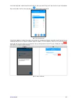
DIGITAL OUTPUT
Alarm Status Mode Connection
The connection to the Digital Output in the Alarm Status mode is made at the terminals
according to the following image. To use the Digital Output, you must power the device
with an external power supply source. The source used must be capable of supplying
current compatible with the load used in the Digital Output.
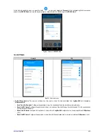
Auxiliary Electronic Switch Mode Connection
The connection to the Digital Output in the Auxiliary Electronic Switch Mode, used to power current transmitters, is made at the terminals according
to the figure below. To use the Digital Output, you must power the device with an external power supply source. The source used must be able to
provide current compatible with the number of transmitters used.
Fig. 38
– Auxiliary electronic switch mode connection
DIGITAL INPUT
PNP Connection
The connection to the Digital Input using a PNP-type sensor is made at the terminals
according to the following image.
NPN Connection
The connection to the Digital Input using a NPN-type sensor is made at the terminals
according to the following image.