~ 37 ~
NOVATEK-ELECTRO
UBZ-304
When disabling the load relay in the event of fault, UBZ records in its memory the code of the fault, the value of
the parameter on which the fault occurred and time of occurrence.
N o te
–
The fault time is determined by internal clock of UBZ.
Number of simultaneously stored fault codes is 50. In case of subsequent faults occur, the fault information is
recorded in place of the oldest fault
To view the log, it is necessary to press button
RES/MEM/SEL
.
Red LED
SETUP
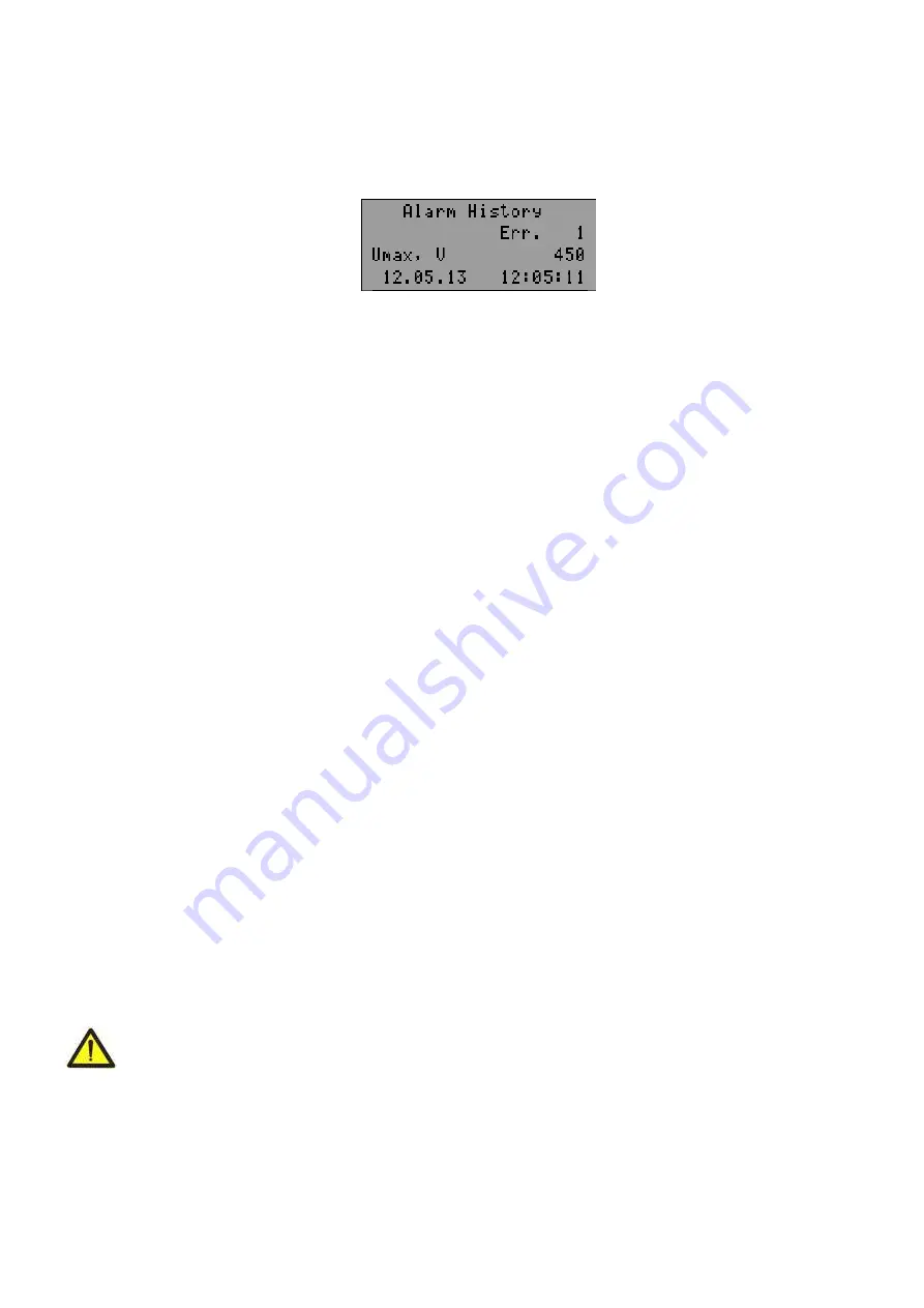
will on in flashing mode, and UBZ indicators will display the latest fault (Fig.5.18).
Line 1
–
indication of mode (alarm logbook);
Line 2
–
number of the fault (1
–
means the most recent fault);
Line 3
–
mnemonic of the fault as per Table 5.13 and the parameter value at the moment of the fault occurrence;
Line 4
–
time and date of the fault.
Figure 5.18
–
Display in the view mode of the fault logbook
View the fault logbook by pressing the
UP
or
DOWN
button.
To exit the view log mode, press the button
RES/MEM/SEL
or exit will be automatically in 30 seconds after the
last pressing of any button.
Register addresses to read data log of faults via MODBUS Protocol are given in Table 5.9.
5.7 MOTOR CONTROL ON UBZ FRONT PANEL
Depending on the value of the parameter “MotorOp UBZ”, you can control the
load relay of UBZ by
simultaneously pressing the
UP
and
DOWN
buttons:
–
“Off”
- no reaction;
–
“Start” (
motor start is enabled) - the load relay will enabled if ARS time has not finished;
–
“Stop” (
motor emergency shutdown) - the load relay will disabled with the issuance of fault code
“Stop
nAR”).
The restart of the motor is possible only after de-energizing and re-energizing of UBZ unit;
–
“St<>” (
motor start and shutdown is permitted) - the load relay is disabled with issuance of code
“Stop
Motor”.
To enable it, press again
UP
and
DOWN
buttons.
N o te
–
in case of selection of parameter
“Start>power”= “
St
Off ” (
after energizing, start of the motor manually on
the front panel of UBZ) and
“MotorOp UBZ”=
“Off” (
the motor control manually is disabled) the load relay will not
turn on.
5.8 MOTOR CONTROL USING ANALOG INPUTS
The motor control algorithms by the analog inputs "0-20 mA" and "0-10 V" are shown in Table 3.6.
After the motor stopping according to emergency level the countdown for ARS will only start after going out the
parameter value of the emergency zone.
If after the motor switching off by the alarm level the parameter value is between the levels on and off for the
motor, then:
–
green LED "
Power relay
" blinks;
–
red LED "
FAULT
" is off;
–
the fault code is displayed on LCD.
N o te
–
In this state of UBZ it is possible to do early motor enabling by buttons on the front panel or by remote
control.
6 MAINTENANCE
6.1 SAFETY PRECAUTIONS
THE TERMINALS AND THE PRODUCT INTERNAL ELEMENTS CONTAINS POTENTIALLY LETHAL
VOLTAGE.
DURING MAINTENANCE IT IS NECESSARY TO DISABLE THE PRODUCT AND
CONNECTED DEVICES FROM THE MAINS
Maintenance of the unit should be performed by persons admitted to the operation and have the appropriate
permission. The recommended frequency of maintenance is every six months.
6.2 MAINTENANCE PROCEDURE:
1) check the wires connection reliability, if necessary
–
clamp with force as specified in Table 3.1;
2) check visually the housing integrity;
3) if necessary, wipe with cloth the front panel and the unit housing.


