~ 17 ~
NOVATEK-ELECTRO
UBZ-304
Control algorithm
Input U
ALG
0
2
0
0
–
"Off"
–
control is off;
1
–
"OffUP"
–
the motor is off when
the voltage is higher than the
upper threshold and it is on when
the voltage is lower than the lower
threshold;
2
–
"OnUP"
–
the motor is on when
the voltage is higher than the
upper threshold and it is off when
the voltage is less than the lower
threshold.
239
Entry in faults logbook
Input U log
0
1
0
0
–
"OffWr"
–
motor cutoff is
considered the fault but not
recorded in the fault logbook;
1
–
"OnWr"
–
motor cutoff is
considered the fault and is
recorded in the fault logbook.
240
Serviceability check of
external magnetic
starter (MS)
Cont Cont
0
1
1
0
–
"Off"
–
check is disabled;
1
–
"On"
–
check is enabled.
241
Energy meters reset
Energy
RESET
0
1
0
0
–
"Off";
1
–
"On"
–
reset.
242
Notes:
1
–
Indicator light turns off if the line supply voltage is lower than 250 V.
2
–
Parameter change will happen after turning off and repeated energizing or fulfillment of "UBZ RESTART" command
3.4 PROTECTION FUNCTIONS
3.4.1 Protection Types
UBZ performs the following protection types for electric motors:
–
over-current protection in phases;
–
ground fault protection (for zero-sequence current);
–
for negative-sequence current;
–
for exceeding negative-sequence current factor to negative-sequence voltage factor;
–
for thermal overload;
–
undercurrent protection in phases;
–
delayed starting (rotor blocking);
–
overheating of windings;
–
for minimum line voltage;
–
for maximum line voltage;
–
for line voltage imbalance (negative sequence voltage protection);
–
for improper phase sequence;
–
for decreasing of mains frequency lower that setting;
–
for increasing of mains frequency higher that setting;
–
for minimum insulation resistance of the motor winding;
–
for the motor phase loss (protection is operated when the motor current is disabled in one (two) phase).
3.4.2 Maximum phases current protection
Maximum current protection on phase is three phase. It is enabled when one, two or three current values reach
the actuation set-point.
The protection has time delay. The time delay can be definite (constant) or dependent (inverse-definite -
SIT
;
very inverse-definite -
VIT
or
LTI
; extremely inverse-definite -
EIT
; ultra inverse-definite -
UIT
, time delay of
RI
type)
- curves are shown in Appendix
А
.
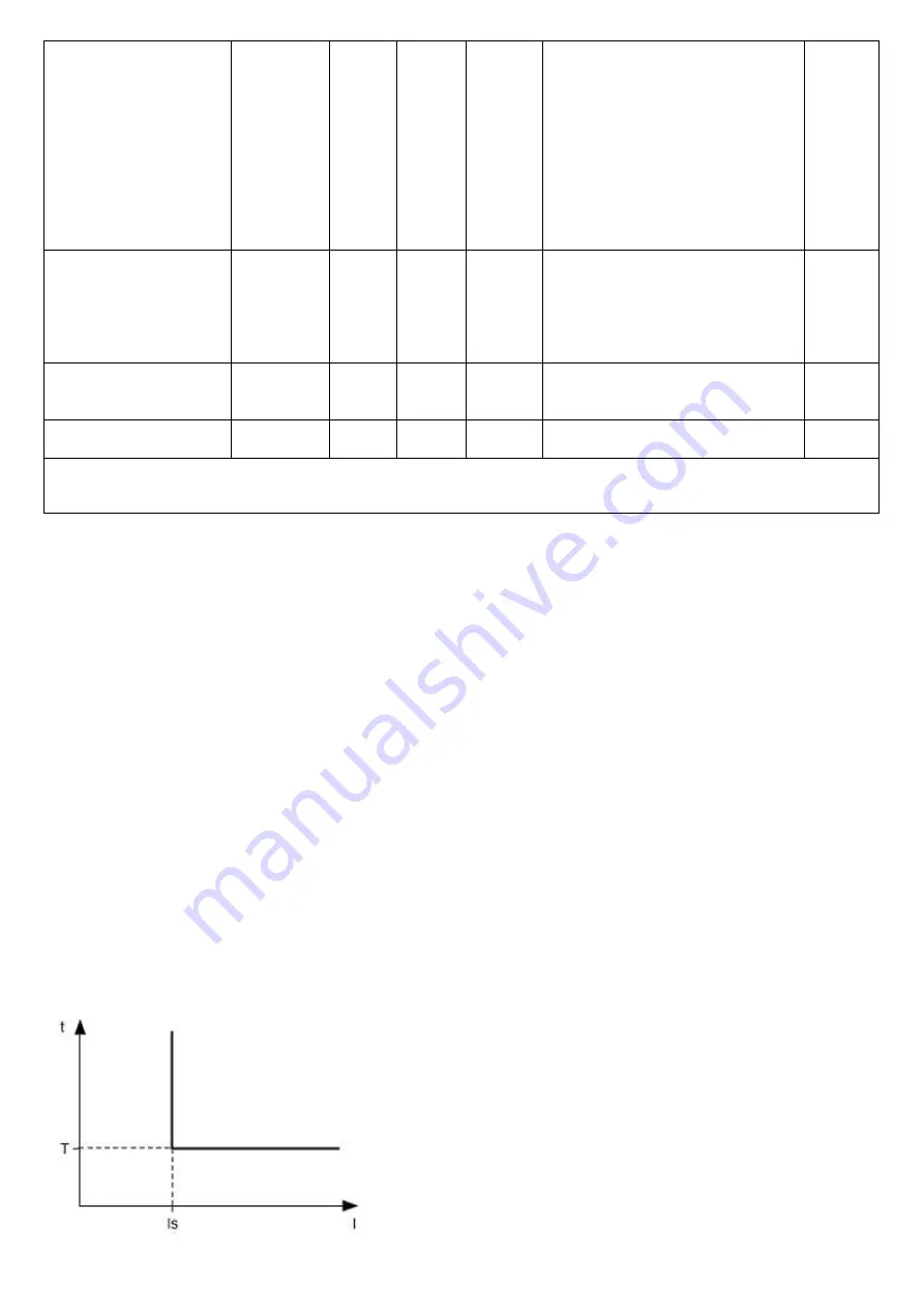
In case of the protection with definite time delay the motor is off
when the current of one phase is more than specified for the time T
(“Imax delay” parameter
).
Is = “Imax coef” (
tripping ratio);
* “Rated Inom” (
motor rated
current), and T is the delay time of the protection operation
(“Imax
de
lay“).
Example: When
“Imax coef“ = 4.0, “Rated Inom” = 10, “Imax
delay“ = 10.0,
the motor will switch off in 10 seconds after one of the
phase currents exceeds 40 Amp.