background image


Northstar 

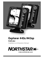
Explorer 443s/443sp

 Installation and Operation Manual

Contents

1 Introduction ..........................................................................................................................................5

2 Getting started ......................................................................................................................................6

2-1 Simulation Mode . . . . . . . . . . . . . . . . . . . . . . . . . . . . . . . . . . . . . . . . . . . . . . . . . . . . . . . . . . . . . . . . . 7

3 Operation ..............................................................................................................................................7

3-1 Alarms . . . . . . . . . . . . . . . . . . . . . . . . . . . . . . . . . . . . . . . . . . . . . . . . . . . . . . . . . . . . . . . . . . . . . . . . . . . . 8
3-2 HISTORY screen operation . . . . . . . . . . . . . . . . . . . . . . . . . . . . . . . . . . . . . . . . . . . . . . . . . . . . . . . . 9
3-3 HISTORY screen interpretation  . . . . . . . . . . . . . . . . . . . . . . . . . . . . . . . . . . . . . . . . . . . . . . . . . . 10
3-4 ZOOM screen  . . . . . . . . . . . . . . . . . . . . . . . . . . . . . . . . . . . . . . . . . . . . . . . . . . . . . . . . . . . . . . . . . . . 13
3-5 SONAR screen . . . . . . . . . . . . . . . . . . . . . . . . . . . . . . . . . . . . . . . . . . . . . . . . . . . . . . . . . . . . . . . . . . . 14
3-6 NAVIGATE screen . . . . . . . . . . . . . . . . . . . . . . . . . . . . . . . . . . . . . . . . . . . . . . . . . . . . . . . . . . . . . . . . 15
3-7 DATA screen . . . . . . . . . . . . . . . . . . . . . . . . . . . . . . . . . . . . . . . . . . . . . . . . . . . . . . . . . . . . . . . . . . . . . 16
3-8 RANGE menu . . . . . . . . . . . . . . . . . . . . . . . . . . . . . . . . . . . . . . . . . . . . . . . . . . . . . . . . . . . . . . . . . . . . 16

4 SETUP menu ......................................................................................................................................... 17

4-1 ALARMS menu  . . . . . . . . . . . . . . . . . . . . . . . . . . . . . . . . . . . . . . . . . . . . . . . . . . . . . . . . . . . . . . . . . . 18
4-2 UNITS menu . . . . . . . . . . . . . . . . . . . . . . . . . . . . . . . . . . . . . . . . . . . . . . . . . . . . . . . . . . . . . . . . . . . . . 19
4-3 FISH SYMBOL . . . . . . . . . . . . . . . . . . . . . . . . . . . . . . . . . . . . . . . . . . . . . . . . . . . . . . . . . . . . . . . . . . . .20
4-4 CONTRAST menu  . . . . . . . . . . . . . . . . . . . . . . . . . . . . . . . . . . . . . . . . . . . . . . . . . . . . . . . . . . . . . . .20
4-5 ZOOM SPLIT . . . . . . . . . . . . . . . . . . . . . . . . . . . . . . . . . . . . . . . . . . . . . . . . . . . . . . . . . . . . . . . . . . . . .20
4-6 LOG menu  (Explorer 443sp ONLY)  . . . . . . . . . . . . . . . . . . . . . . . . . . . . . . . . . . . . . . . . . . . . . . 21
4-7 INSTALL menu . . . . . . . . . . . . . . . . . . . . . . . . . . . . . . . . . . . . . . . . . . . . . . . . . . . . . . . . . . . . . . . . . . . 21
4-8 CALIBRATION menu . . . . . . . . . . . . . . . . . . . . . . . . . . . . . . . . . . . . . . . . . . . . . . . . . . . . . . . . . . . . .22
4-9 Resetting to Factory Defaults . . . . . . . . . . . . . . . . . . . . . . . . . . . . . . . . . . . . . . . . . . . . . . . . . . . .23

5 Installation .......................................................................................................................................... 23

5-1 What comes with the Explorer 443s/443sp? . . . . . . . . . . . . . . . . . . . . . . . . . . . . . . . . . . . . . .23
5-2 Options and Accessories . . . . . . . . . . . . . . . . . . . . . . . . . . . . . . . . . . . . . . . . . . . . . . . . . . . . . . . . . 24
5-3 Mounting the Explorer 443s/443sp Display Unit . . . . . . . . . . . . . . . . . . . . . . . . . . . . . . . . . 24
5-4 Wiring Connection . . . . . . . . . . . . . . . . . . . . . . . . . . . . . . . . . . . . . . . . . . . . . . . . . . . . . . . . . . . . . .25
5-5 Connecting an Explorer 443s/443sp to other instruments  . . . . . . . . . . . . . . . . . . . . . . . 26

Appendix A - Specifications ..................................................................................................................... 27

Appendix B - Troubleshooting ................................................................................................................. 28

Summary of Contents for EXPLORER 443S

Page 1: ...www northstarnav com Explorer 443s 443sp Fishfinder Installation and Operation Manual ...

Page 2: ...void possible injury or death WARNING WARNINGindicatesapotentiallyhazardoussituationwhich ifnotavoided could result in death or serious injury CAUTION CAUTION indicates a potentially hazardous situation which if not avoided could result in minor or moderate injury CAUTION CAUTION used without the safety alert symbol indicates a potentially haz ardous situation which if not avoided may result in pr...

Page 3: ... 16 4SETUPmenu 17 4 1 ALARMS menu 18 4 2 UNITS menu 19 4 3 FISH SYMBOL 20 4 4 CONTRAST menu 20 4 5 ZOOM SPLIT 20 4 6 LOG menu Explorer 443sp ONLY 21 4 7 INSTALL menu 21 4 8 CALIBRATION menu 22 4 9 Resetting to Factory Defaults 23 5Installation 23 5 1 What comes with the Explorer 443s 443sp 23 5 2 Options and Accessories 24 5 3 Mounting the Explorer 443s 443sp Display Unit 24 5 4 Wiring Connection ...

Page 4: ...ected by many factors including the type and location of the transducer and water conditions Ensure that the transducer is located and used correctly Fuel Computer Do not rely on the fuel computer as the sole source of information regarding available fuel onboard Fuel economy can change drastically depending on boat loading and sea conditions Fuel Computer information should be supplemented by vis...

Page 5: ...y air in the water e g from another boat s wake or by mud in the water Important It is vital to the performance of the fishfinder that the transducer is installed in the best location Please follow the instructions in the Transducer Installation manual very carefully All of the Northstar 400 Series fishfinders use proprietary SBN Technology for sonar processing to improve signal enhancement bottom...

Page 6: ... power cable has a black 8 pin LT connector plug Push this plug into the lower socket which has a black nut and is located on the rear of the display unit then turn the collar to lock Make sure that the collar is secure for a watertight connection One end of the transducer cable has a blue 8 pin LT connector plug Push this plug into the upper socket which has a blue nut and is located on the rear ...

Page 7: ...hows the current setting Press repeatedly until the desired backlighting level is achieved The backlight bar will disappear two seconds after the last press An internal simulator allows users to learn how to operate the fishfinder off the water In Simulation mode the word SIMULATION flashes on the bottom of the screen The fishfinder generates data so that all the main screens appear to be operatio...

Page 8: ...nabled to automatically detect certain conditions such as the water being too shallow The trigger settings for the alarms can be defined to suit the boat and individual preferences The fishfinder has six alarms TOO SHALLOW TOO DEEP FISH ALARM TEMP VALUE TEMP RATE and LOW BATTERY The alarm symbols and beeper cycles for all of the alarms are shown in section 4 1 The FISH ALARM is three short beeps t...

Page 9: ...o use a fishfinder or when travelling at speed In Manual Gain the user can adjust the gain to compensate for water depth and clarity Manual settings range from 1 to 9 High settings may amplify normal background noise until it appears as random pixels on the screen The ideal setting produces only a small number of random pixels Normally the best results with a fishfinder are obtained in Manual Gain...

Page 10: ...ates a weak return signal that turns on the first pixel on the fishfinder screen As the boat moves closer to the fish the distance between the transducer and the fish reduces and the return signal is displayed at progressively shallower depths producing the start of an arch When the fish is directly beneath the transducer and in the middle of the beam then the returned signal is even stronger so t...

Page 11: ...r object The area covered by the ultrasonic beam is approximately cone shaped and echoes are strongest in the middle The clarity of water Particles or air in the water reduce the strength of the returned echo The composition or density of the object or bottom Mud weed and sand bottoms tend to weaken and scatter the sonar signal which results in weaker returns Rock or coral bottoms concentrate the ...

Page 12: ...ing for small objects including fish users should consider that there are places where fishfinders cannot see Shadow where objects are hidden in the bottom echo These fish will be hidden in the bottom echo 1 minute ago 30 seconds ago Now When the fish symbol option is ON any echo returned that fits the profile of a fish is displayed on the screen with a fish symbol Air in water e g from wake North...

Page 13: ... in this case the section between 50 ft and 100 ft The zoom section shows the area of interest such as fish or features close to the bottom in greater detail than the HISTORY screen BottomLock The zoom bar is normally locked to the bottom Bottom Lock so that the bottom is always displayed in the zoom section regardless of changes in depth To turn Bottom Lock off press then move the zoom bar to the...

Page 14: ...ower trace Small strong echo e g fish This usually flashes on and off as the ultrasonic pulse strikes the fish Large strong signal e g bottom Shading Bar RecognisingtheTypeofFish Different species of fish have different sizes and shapes of swim bladders The air in the swim bladder reflects the ultrasonic pulse so the strength of the echo varies between fish species according to the size and shape ...

Page 15: ...l result in more detail being shown on the fishfinder display Decreasing the gain will reduce detail being shown See Changing the Gain Mode in section 3 2 for more information on changing Gain settings 3 6NAVIGATEscreen Select MAIN MENU NAVIGATE to display the NAVIGATE screen The NAVIGATE screen displays useful information while travelling at speed It prominently displays the water depth the boat ...

Page 16: ... be reset manually e g to record total mileage during a season or the distance travelled on this trip Note That the units displayed on each Log will correspond with the Speed Speed 443sp ONLY can be displayed in knots KN miles per hour MPH or kilometres per hour KPH Use the SETUP UNITS SPEED menu to select the desired speed units see section 4 2 Battery Depth Speed Temperature Temperature Graph Lo...

Page 17: ...rature speed and fuel see section 4 2 Turn the key beep on or off Choose the fish symbol see section 4 3 Choose the contrast level see section 4 4 Turn Simulation mode on or off Turn Zoom Split on or off see section 4 5 Select the Trip Log or the Total Log see section 4 6 Zero Trip Log or zero all logs see section 4 6 Select language setup the keel offset see section 4 7 Calibrate speed and temper...

Page 18: ...ay the available alarms Press or to highlight an option When an alarm condition is met then The beeper sounds The ALARMS menu is displayed on the screen with the activated alarm symbol s flashing Press any key to acknowledge the alarm stop the beeping and remove the ALARMS menu This does not disable the alarm The symbol will continue to flash until the alarm condition is no longer present Note The...

Page 19: ...er value for an Alarm press or to increase or decrease the trigger value The alarm trigger value is retained even when the alarm is disabled Select MAIN MENU SETUP UNITS to define the units for depth temperature speed and fuel 4 2UNITSmenu Press or to highlight an option DEPTH Can be displayed in units of feet FT fathoms FA or metres M Press to select the required depth units TEMPERATURE Can be di...

Page 20: ...returned that match the profile of a fish as a fish symbol in one of three sizes as above The depth of the fish is shown to the left of the symbol Echoes which are not recognised as fish are displayed as dots on the screen Use the FISH FILTER setting to adjust the fish detection see section 4 9 Select MAIN MENU SETUP CONTRAST to display the contrast setting box and the current setting The contrast...

Page 21: ...x ZERO ALL LOGS YES appears Press to select YES or NO Then press or to exit Use this menu at installation time to select the language and to enter the keel offset value the number of engines and the fuel tank size The INSTALL menu can also be used to calibrate the water temperature and boat speed Select MAIN MENU SETUP INSTALL to display the menu 4 7INSTALLmenu Press or to highlight an option LANG...

Page 22: ...ater temperature boat speed fuel readings and the fuel flow filter Select MAIN MENU SETUP INSTALL CALIBRATION to display the calibration menu CalibratingtheFishFilter Use this to adjust the fish detection when FISH SYMBOLS are switched on Fish detection depends on water clarity fish species and fish size Calibration may be required if too little or too much fish are being detected Select more fish...

Page 23: ...LARMS Shallow Alarm OFF Shallow Alarm Value 10 ft Deep Alarm OFF Deep Alarm Value 60 ft Fish Alarm OFF Temp Change Alarm OFF Temp Change Alarm Value 5 0 F Temp Alarm OFF Temp Alarm Value 80 F Low Battery Alarm OFF Battery Alarm Value 11 5 Volts FISH SYMBOL INSTALL Keel Offset 0 0 ft Fish Filter Correct installation is critical to the performance of the Explorer 443s 443sp There are two components ...

Page 24: ...the mounting bracket onto the boat using the three stainless steel screws Do not overtighten as the bracket may not rotate 2 Push the display unit onto the mounting bracket and tighten it firmly using the knob on the mounting bracket 3 Attach the cables 5 3MountingtheExplorer443s 443spDisplayUnit RemovingtheExplorer443s 443sp The Explorer 443s 443sp can be removed after each use for protection aga...

Page 25: ...fit a 12 V relay Consult your Northstar dealer for more advice NMEAInstruments 443spONLY Use the white wire if desired to connect the fishfinder to other NMEA instruments such as Northstar s depth repeater See section 5 5 for more information CAUTION If possible route the transducer cables away from other wiring on the boat Electrical noise from engine wiring bilge pumps and other electrical equip...

Page 26: ...ments an NMEA line can be read and displayed by another instrument that accepts NMEA 0183 Version 2 Depth speed and temperature data is output by the Explorer 443sp and can be read and displayed by the Northstar Explorer R310 Explorer D210 GPS Chartplotter 500 series or other NMEA instrument Explorer R310 Repeater for depth speed water temperature and battery voltage Can accept many other NMEA dat...

Page 27: ...soundings second Receiver sensitivity Better than 10 micro volts RMS Appendix A Specifications Standards Compliance EMC USA FCC Part 15 Class B Europe CE IEC60945 New Zealand Australia C Tick CISPR 22 Environment IPx6 IPx7 Temperature measurement range 32 to 99 9 F 0 to 37 7 C Resolution 0 1 units Speed range 1 to 50 kn 57 5 mph 96 6 kph Speed resolution 0 0 to 9 9 10 to 50 Communications NMEA 018...

Page 28: ...wer cable from end to end for damage such as cuts breaks or squashed sections e Ensure that the red wire is connected to the positive battery terminal and the black wire to the negative battery terminal If wired for the Auto Power option ensure the yellow wires are connected to ignition circuit Also check the boat s main switch circuit see section 5 4 f Check for corrosion on the power cable LT co...

Page 29: ...on 2 f Check the transducer and power cable LT connectors at the back of the display unit are securely plugged in and the collar is locked in place The collar must be secure for watertight connection g Inspect the transducer and power cables from end to end for damage such as cuts breaks or squashed sections h Ensure there is not another fishfinder or depth sounder turned on which may interfere wi...

Page 30: ......

Page 31: ......

Page 32: ...ROPE Unit 2 Ocean Quay Belvidere Rd Southampton SO14 5QY ENGLAND Ph 44 2380 339922 Fax 44 2380 330345 northstaruk northstarnav com AUSTRALIA PO Box 479 Gladesville NSW 2111 AUSTRALIA Ph 61 2 9879 9060 Fax 61 2 9879 9009 northstaraus northstarnav com NEW ZEALAND PO Box 68 155 Newton Auckland Auckland NEW ZEALAND Ph 64 9 481 0500 Fax 64 9 481 0590 northstarnz northstarnav com ...

Reviews: