North Ridge Pumps seepex BN Series Operating And Maintenance Instructions Manual Download Page 29

8.
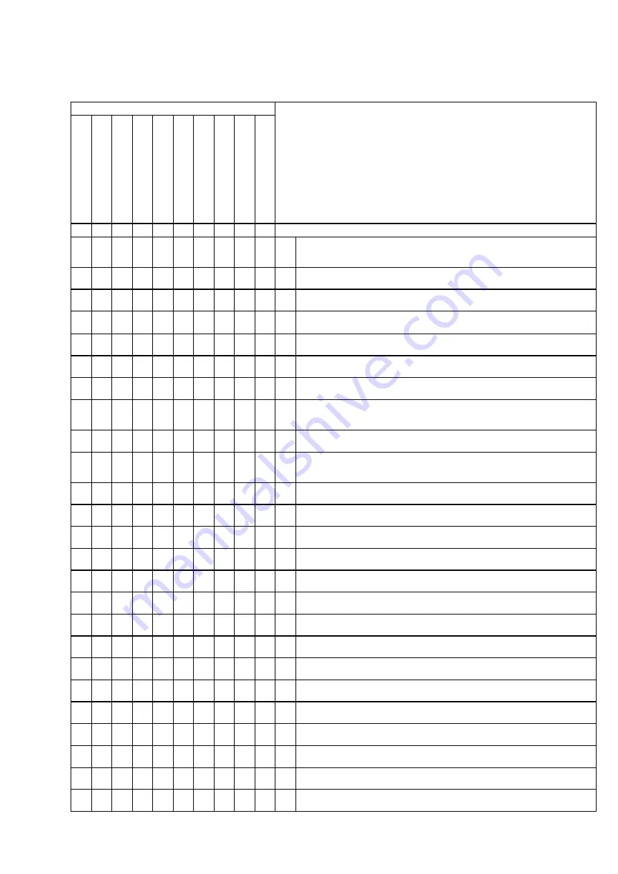
Breakdown, reasons, remedies

Breakdown

pum

p has no sucti

o

n

pum

p conveys ir

re

gular

ly

the conveying capacity is not 

achieved

pr

essur

e

 is not achieved

pum

p does not star

t

pum

p has sei

z

e

d or

 has 

stopped conveying

pum

p oper

a

tes noi

si

ly

mo

to

r b

e

c

o

me

s

 t

o

o

 w

a

rm

the stator

 wear

s out ear

ly

shaft sealing leaks

1

2

3

4

5

6

7

8

9

10

Reasons / Remedies

‰

‰

a

‰

b

‰ ‰ ‰

‰ ‰

c

‰ ‰ ‰

‰

d

‰ ‰ ‰

e

‰

‰

‰

f

‰ ‰

g

‰

‰ ‰

‰ ‰

h

‰ ‰ ‰

‰

‰

i

‰ ‰

j

‰

‰

k

‰ ‰

‰

l

‰

m

‰

‰

‰ ‰

‰

n

‰

‰ ‰

‰

o

‰

‰

‰ ‰

p

‰

‰

‰

‰

q

‰

‰ ‰

‰ ‰

r

‰

‰

‰

‰

‰

s

‰

‰ ‰

‰

t

‰

‰

‰ ‰

u

‰

‰ ‰

‰ ‰

v

‰ ‰

‰ ‰

w

‰

‰

x

‰

y

seepex progressive cavity pumps will operate trouble-free if 
they 
are used in accordance with our data sheet (see item 9) and 
our operating and maintenance instructions:

Check rotational direction of the pump per data sheet and nameplate. 
In case of wrong direction, change wiring of motor.

Suction pipe or shaft sealing leak. Eliminate the leakage.

Suction head too high (item 6.5.3.1). Check suction head with vacuum gauge. 
Increase the suction pipe diameter and fit larger filters. Open the suction valve 

Viscosity of the liquid too high. 
Check and accommodate per data sheet.

Wrong pump speed.
Correct pump speed per data sheet.

Avoid inclusions of air in the conveying liquid.

Pressure head too high (point 6.5.3.2). Check pressure head with manometer. 
Reduce the pressure head by increasing the pressure pipe diameter or by 
shortening the pressure pipe.

Pump runs partially or completely dry (point 6.5.2). Check flow in the suction 
chamber. Install dry running protection TSE.

Check coupling, possibly pump shaft is misaligned to drive. Check whether 
coupling gear is worn. Realign coupling. The coupling gear has perhaps to be 
replaced.

Speed too low. Increase the speed when high suction performances are 
required and when the liquid is very thin.

Speed too high. Reduce the speed when pumping products with high 
viscosities - danger of cavitation.

Check the axial play in the coupling rod linkage. Check that the bush has been 
installed correctly see document OM.PJT.__e item 2.2

Check for foreign substances in the pump. Dismantle the pump, remove 
foreign substances and replace worn parts.

Stator or rotor worn. Dismantle the pump and replace defective parts.

Joint parts worn. Replace worn parts and fill with special pin joint grease .

Suction pipework partially or completely blocked. Clean suction pipework.

Temperature of the pumping liquid too high. Excessive expansion of the stator. 
Check temperature and install rotor with diameter smaller than specified.

Gland packing too strongly tightened or worn. Ease or tighten stuffing box. 
Replace defective packing rings.

Solid contents and/or size of solids too large. Reduce pump speed and install 
perhaps a screen with suitable meshes. Increase fluid share.

When the pump is non operational the solids settle out and become hard. 
Clear and flush the pump immediately.

The liquid becomes hard when temperature falls below a certain limit. Heat the 
pump.

Stator swollen and unsuitable for the pumped liquid. Select a suitable stator 
material. Use perhaps rotor with diameter smaller than specified.

The bearing in the drive casing of the pump or in the drive engine is defective. 
Replace bearing.

Mechanical seal defective. Check seal faces and O-rings. If necessary replace 
corresponding defective parts.

Adhesion between rotor and stator  excessive (as delivered). 
Lubricate (soft soap, genuine soap) between stator and rotor. 
Then turn the pump by means of the  tool W2 .

OM.REC.01e

1 (1)

A / 05.01.95

Operating and Maintenance Instructions
Progressive Cavity Pump

Dokument

document

Blatt

sheet

Ausgabe

issue

Summary of Contents for seepex BN Series

Page 1: ...mp Range BN Non binding Operating and Maintenance Instructions This operating and maintenance instruction includes important safety information and instructions for installation commissioning operatin...

Page 2: ...to 1 6L OM PJT 02e BN 05 24 to 300 6L 7 2 0 OM HBD 01e Holding Band Re assembly 8 0 0 OM REC 01e Breakdown reasons remedies 9 0 0 OM ACC 01e Auxiliary seepex documentation Sectional drawing and parts...

Page 3: ...2 7 EEC Machine Directive 1 2 7 1 Manufacturer s Declaration seepex Manufacturer s Declaration as required by the EEC Machine Directive 89 392 EEC Appendix II B The seepex machines delivered in accord...

Page 4: ...late mounted the machine 1 2 10 Technical Data Sheet see Point 9 1 2 11 Performance Data Load Index Power Consumption are indicated in the associated data sheet Point 9 1 2 12 Sound Pressure Level The...

Page 5: ...nformation remains legible 2 2 Personnel Qualifications and Training Personnel charged with operation maintenance inspection and assembly must be in possession of the appropriate qualifications for th...

Page 6: ...and become sufficiently familiar with the machine As a basic rule the machine must be brought to a standstill before work is carried out Always comply with the de commissioning procedure described in...

Page 7: ...ttached information notices and symbols 3 4 Intermediate Storage Preservation Unless otherwise indicated in the data sheet seepex machines are provided with preservation only for the duration of trans...

Page 8: ...suction and pressure side in every position of the eccentric screw even when the pump is stationary The pump owes its high suction capacity to this sealing between the suction and pressure sides 4 2...

Page 9: ...bly of mechanical protective devices e g V belt or coupling protection space required for handling the mounting tools e g sufficient wall clearance 5 2 1 3 Space Allowing Disassembly of Stator P A spe...

Page 10: ...rom seepex so that the frequency inverter can be tuned on the seepex test field along with a trial run Ensure that customer supplied frequency inverters comply with the starting torque and running pow...

Page 11: ...even if an air column up to the liquid level remains 6 2 3 2 Pump with plastic rotor Pump with plastic rotating unit CAUTION Important information about commissioning can be taken from the document OM...

Page 12: ...pump increases the friction between rotor and stator quickly causing an unacceptably high temperature to develop on the inner surface of the stator This overheating leads to burning of the stator mate...

Page 13: ...d pressure side or shut off directly behind the pump connections Drain any residual liquid in the pump casing by opening removing the screwed sealing plugs 705 and 502 sealing rings 706 and 503 CAUTIO...

Page 14: ...grease and lubricated for the expected duration of service The seepex joint grease specified in the index of these operating instructions should be used exclusively for any required maintenance work...

Page 15: ...the pressure flange 700 pour the antiseize agent into the opening between rotor and stator on the pressure flange side Several clockwise see Point 6 2 5 revolutions of the rotor will then distribute t...

Page 16: ...ay that it cannot tip over or fall down during the re assembly of the drive and all pump components 7 4 1 Lantern 200 Drive ANT Assembly Clean flange bearing surfaces FLS centering diameter and output...

Page 17: ...assembly Maintenance tip Disassembly of the stator can be facilitated con siderably by first moistening the inner surface of the stator with antiseize agent soft or liquid soap Before removing the pre...

Page 18: ...rease and lubricated for the expected duration of service The seepex joint grease specified in the index of these operating instructions should be used exclusively for any required maintenance work CA...

Page 19: ...p Before removing the pressure flange 700 pour the antiseize agent into the opening between rotor and stator on the pressure flange side Several clockwise see Point 6 2 5 revolutions of the rotor will...

Page 20: ...a way that it cannot tip over or fall down during the re assembly of the drive and all pump components 7 4 1 Lantern 200 Drive ANT Assembly Clean flange bearing surfaces FLS centering diameter and ou...

Page 21: ...Disassembly of the stator can be facilitated con siderably by first moistening the inner surface of the stator with antiseize agent soft or liquid soap Before removing the pressure flanges 700 pour t...

Page 22: ...k back retaining sleeve 401 with tool chisel WM 7 3 6 3 Separation of Joint Eject coupling rod pins 402 Pull coupling rod 400 out of joint top 1 4 Guide bushes 403 Dismantling Press out guide bushes 4...

Page 23: ...403 in using tool W4 see Point 9 Fill joint top with joint grease 098 see index for special grease Coupling rod 400 Retaining sleeve 401 Securing of retaining sleeve Secure offset by 2x180 with tool...

Page 24: ...s releases the coupling rod 400 which can then be extracted CAUTION To guarantee the proper function of the joints it is advisable to renew the coupling rod pins 402 guide bushes 403 and coupling rod...

Page 25: ...ble to renew the coupling rod pins 402 guide bushes 403 and coupling rod bushes 404 all at the same time Joint head on rotor 600 and plug in shaft 307 Press guide bushes 403 in by only 2 3 of their le...

Page 26: ...tool centre punch WK For rotors made of synthetic material secure using set screw 426 During this process point of set screw presses into the synthetic surface X Set screw 426 is medium strengh secure...

Page 27: ...rs al joint sleeve and is stuck in position Incorrect Holding band HBD is too slack and liable to slip Incorrect Holding band HBD is too tight Universal joint sleeve will be damaged sheared off Foldin...

Page 28: ...olding band The holding band must run all the way round the groove of the universal joint sleeve The holding band HBD must be bent back and sheared off at the holding band loop SCL in such a way that...

Page 29: ...liquid is very thin Speed too high Reduce the speed when pumping products with high viscosities danger of cavitation Check the axial play in the coupling rod linkage Check that the bush has been inst...

Page 30: ...Operating Instructions seepex Machine Auxiliary documentation Dokument document Ausgabe issue Blatt sheet OM ACC 01e A 13 01 95 1 1 9 Auxiliary seepex documentation...

Page 31: ......

Page 32: ...casing carter d aspiration 1 501 Sauggeh usedichtung casing gasket tanch it du carter d aspiration 3 502 Verschlussschraube screwed plug bouchon de vidange 3 503 Dichtring sealing ring joint d tanch i...

Page 33: ......

Page 34: ...joint d tanch it 4 506 6kt Schraube hexagon bolt vis 4 507 F cherscheibe fan type lock washer rondelle dents chevauchantes ext rieures 4 509 6kt Mutter hexagon nut crou 2 510 Reinigungsdeckel cleanou...

Page 35: ...azard due to its toxicity explosive ness or combustibility The leakage must be dis posed of at a safe location Always pay due regard to the applicable national standards and specifica tions 2 Shaft Se...

Page 36: ...re 2 Monitoring during Operation 2 1 Checking for Leaks Gland packings must be checked for leaks at regular intervals while the pump is running In the case of excessive leakage overpressure in suction...

Page 37: ...jecting edges and burring that could damage the shaft sealing elements Remove shaft sealing SEA from the plug in shaft 4 2 Re assembly CAUTION As a basic rule only packing materials conforming to the...

Page 38: ...nents that may contact leakage must be resistant to corrosion or be protected accordingly Mechanical seal leakage must be drained in a safe and proper manner 4 Flushing or circulation of single acting...

Page 39: ...ove plug in shaft 307 burrs and roughness and clean the unit Check adjust set dimension of mechanical seal on plug in shaft 307 Moisten plug in shaft 307 and elastomer parts of mechanical seal with lu...

Page 40: ...o sectional drawing of pump and parts list Part designation Number Rotor 1 600 Stator 2 1 1 601 Universal joint sleeve 1 405 Coupling rod pin 2 402 Guide bush 2 4 403 Coupling rod with coupling rod bu...

Page 41: ...and parts list Part designation Number Rotor 1 600 Stator 2 1 1 601 Universal joint sleeve 2 405 Coupling rod pin 2 402 Guide bush 2 4 403 Coupling rod with coupling rod bush 1 2 400 404 Coupling rod...

Page 42: ...0000 0 00000 0010 0 00000 10 6L 15 6LT PKZ XX 000 5 24 0000 0 XOHV0 2 St ck 10 6 DHS 00 100 BLZ 00 020 2 pieces 10 12 0000 0 00000 0010 0 00000 MHL XX SA 610 WKZ SBD 140 17 6L 30 6LT 26 6L 40 6LT KRZ...

Page 43: ...0 PWZ C6 060 1 24 0020 0 XXXXX 0020 0 XXXXX 0020 0 XXXXX 0020 0 XXXXX 0020 0 XXXXX 2 6 2 12 5 6L 2 24 5 6 MTD L2 060 MTH M8 060 AZV B2 262 MMT M8 060 PWZ C6 060 5 12 0050 0 XXXXX 0050 0 XXXXX 0050 0 X...

Page 44: ...Operating Instructions seepex Machine Manufacturer s documents Dokument document Ausgabe issue Blatt sheet OM MDS 01e A 22 02 95 1 1 10 Manufacturer s documents from sub supplier...

Reviews: