


Page 6
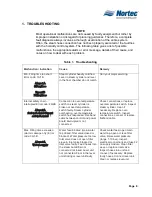
Max. Boil down rate too long
Error code: 4A/4B
Error4B
SteamtimeAlarm
4Asteamtime
Individual heating elements faulty.
Main voltage too low or failure of
a phase (L1, L2 or L3). Steam
line too long or not insulated.
Replace faulty heating elements.
Replace fuses on power board.
Check main voltage and
connections. Maintain maximum
line lengths (max. 15’). Insulate
steam lines.
Max. Drain time exceeded
Error code: 5A/5B
Alarm5Adrain
Error5Bdrain
Drain pump not connected or
faulty. Outlet line from unit kinked
or blocked. Water outlet blocked
(external outlet line or siphon
blocked. Hose to level unit
blocked.
Connect or replace drain pump.
Inspect outlet line from unit,
replace if necessary. Clean water
outlet line and siphon. Clean or
replace hose.
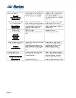
Invalid level
Error code: 6A/6B
Alarm6A
Levelindicat
Error6B
levelindicat
Level unit faulty.
Magnetic field in vicinity of level
unit.
Replace level unit.
Eliminate magnetic field.
Steam pressure (error only)
Error code: 7A/7B
Alarm7A
communication
Steam hose blocked or restricted
(water trap).
Pressure balance adapter into
steam connection fitting blocked.
Duct pressure too high (>1500
Pa).
Inspect steam hose, clean if
necessary and install correctly.
Remove adapter and clean
opening with a needle.
Inspect ventilation settings.
External safety chain
interrupted Error code: none
SafetychainexternalA
Mainsfailure B
Ventilator lock open. Automatic
flow control has responded.
Safeties are open.
Main failure on Unit B.
Switch on ventilator/ventilation
system. Inspect ventilator/filter of
ventilation system. Servicing,
inspect system if necessary.
Inspect voltage supply to Unit B.
Summary of Contents for NH Series
Page 4: ......
Page 6: ...Page 1 10 00 INTRODUCTION ...
Page 7: ...Page 2 Figure 1 NHRS ...
Page 11: ...Page 6 Figure 6 Typical NHRS Installation Sheet 1 of 2 ...
Page 12: ...Page 7 Figure 7 Typical NHRS Installation Sheet 2 of 2 ...
Page 13: ...Page 8 THIS PAGE INTENTIONALLY LEFT BLANK ...
Page 14: ...Page 9 10 10 INSTALLATION PROCEDURES ...
Page 17: ...Page 12 Figure 1 Plumbing Connections ...
Page 23: ...Page 18 Figure 4 Steam Run and Condensate Return Installation Guidelines 1 of 2 ...
Page 24: ...Page 19 Figure 5 Steam Run and Condensate Return Installation Guidelines 2 of 2 ...
Page 28: ...Page 23 Figure 7 On Off Guidelines and Low Voltage Terminal Strip 254 8731 ...
Page 29: ...Page 24 Figure 8 NORTEC Control Guidelines and Wiring Optional ...
Page 31: ...Page 26 Figure 10 NORTEC Humidity Transducer Guidelines and Wiring Option ...
Page 41: ...Page 36 Figure 22 Typical SAM e Duct Installation ...
Page 45: ...Page 40 Figure 25 SAM e Drain Water Cooling ...
Page 49: ...Page 44 THIS PAGE INTENTIONALLY LEFT BLANK ...
Page 50: ...Page 45 10 20 OPERATION ...
Page 60: ...Page 55 Figure 2 Drain Interval Settings ...
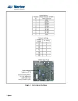
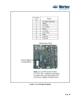
Page 63: ...Page 58 Figure 3 Control Signal Setting ...
Page 65: ...Page 60 THIS PAGE INTENTIONALLY LEFT BLANK ...
Page 66: ...Page 10 30 MAINTENANCE PROCEDURES ...
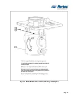
Page 69: ...Page 6 Figure 1 Minor Maintenance with Scale Management Option ...
Page 72: ...Page 6 10 40 TROUBLESHOOTING ...
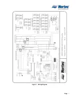
Page 75: ...Page Figure 1 Wiring Diagram ...
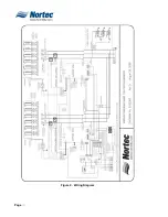
Page 76: ...Page Figure 2 Wiring Diagram ...
Page 81: ...Page 7 THIS PAGE INTENTIONALLY LEFT BLANK ...
Page 82: ...Page 7 10 50 TECHNICAL ...
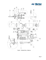
Page 83: ...Page 7 Figure 1 Exploded View Plumbing ...
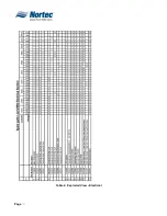
Page 84: ...Page 7 Table 1 Exploded View Plumbing ...
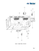
Page 85: ...Page Figure 2 Exploded View Electrical ...


