Page
28
D. MULTIPLE DISTRIBUTOR APPLICATION
(1)
The use of multiple steam distributors can reduce the absorption distance in most
situations. (See Figure 13).
CAUTION
THESE INSTALLATION GUIDELINE APPLY FOR DUCT
VELOCITIES UNDER 2000 FT/MIN (610M/MIN), PLEASE
CONSULT FACTORY FOR HIGHER VELOCITY.
CAUTION
PLEASE MAKE SURE THAT NO OBSTACLES (ELBOW,
FILTER, OR DIFFUSER) ARE LOCATED AFTER THE
DISTRIBUTOR IN THE DIRECTION OF AIRFLOW CLOSER
THAN THE ABSORPTION DISTANCE CALCULATED FOR YOUR
APPLICATION.
CAUTION
UNLESS YOU KNOW THE EXACT ABSORPTION DISTANCE
REQUIRED FOR THE STEAM ABSORPTION INTO THE AIR STREAM,
THE DISTRIBUTOR SHOULD BE LOCATED AT LEAST 8-10FT (2-3M)
AWAY FROM ANY OBSTACLE IT MAY CONDENSE ON (ELBOW,
DIFFFUSER, FILTER, ETC.)
Summary of Contents for NH Series
Page 4: ......
Page 6: ...Page 1 10 00 INTRODUCTION ...
Page 7: ...Page 2 Figure 1 NHRS ...
Page 11: ...Page 6 Figure 6 Typical NHRS Installation Sheet 1 of 2 ...
Page 12: ...Page 7 Figure 7 Typical NHRS Installation Sheet 2 of 2 ...
Page 13: ...Page 8 THIS PAGE INTENTIONALLY LEFT BLANK ...
Page 14: ...Page 9 10 10 INSTALLATION PROCEDURES ...
Page 17: ...Page 12 Figure 1 Plumbing Connections ...
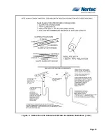
Page 23: ...Page 18 Figure 4 Steam Run and Condensate Return Installation Guidelines 1 of 2 ...
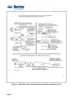
Page 24: ...Page 19 Figure 5 Steam Run and Condensate Return Installation Guidelines 2 of 2 ...
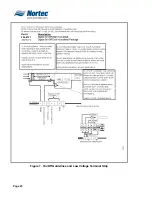
Page 28: ...Page 23 Figure 7 On Off Guidelines and Low Voltage Terminal Strip 254 8731 ...
Page 29: ...Page 24 Figure 8 NORTEC Control Guidelines and Wiring Optional ...
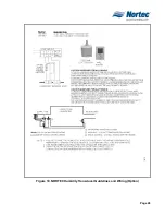
Page 31: ...Page 26 Figure 10 NORTEC Humidity Transducer Guidelines and Wiring Option ...
Page 41: ...Page 36 Figure 22 Typical SAM e Duct Installation ...
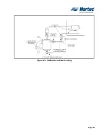
Page 45: ...Page 40 Figure 25 SAM e Drain Water Cooling ...
Page 49: ...Page 44 THIS PAGE INTENTIONALLY LEFT BLANK ...
Page 50: ...Page 45 10 20 OPERATION ...
Page 60: ...Page 55 Figure 2 Drain Interval Settings ...
Page 63: ...Page 58 Figure 3 Control Signal Setting ...
Page 65: ...Page 60 THIS PAGE INTENTIONALLY LEFT BLANK ...
Page 66: ...Page 10 30 MAINTENANCE PROCEDURES ...
Page 69: ...Page 6 Figure 1 Minor Maintenance with Scale Management Option ...
Page 72: ...Page 6 10 40 TROUBLESHOOTING ...
Page 75: ...Page Figure 1 Wiring Diagram ...
Page 76: ...Page Figure 2 Wiring Diagram ...
Page 81: ...Page 7 THIS PAGE INTENTIONALLY LEFT BLANK ...
Page 82: ...Page 7 10 50 TECHNICAL ...
Page 83: ...Page 7 Figure 1 Exploded View Plumbing ...
Page 84: ...Page 7 Table 1 Exploded View Plumbing ...
Page 85: ...Page Figure 2 Exploded View Electrical ...

