


Page 3
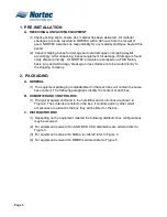
1. PRE-INSTALLATION
A. RECEIVING & UNPACKING EQUIPMENT
(1) Check packing slip to ensure ALL material has been delivered. All material
shortages are to be reported to NORTEC within 48 hours from the receipt of
good. NORTEC assumes no responsibility for any material shortages beyond this
period.
(2) Inspect shipping boxes for damage and note damages on shipping waybill
accordingly. After unpacking, inspect equipment for damage. If damage is found
notify shipper promptly. All NORTEC products are shipped on a FOB factory
basis. Any and all damage, breakage or loss claims are to be made directly to
the shipping company.
2. PACKAGING
A. GENERAL
(1) The equipment packaging is standardized in that each box will contain the same
base content. The following paragraphs identify the content of each box.
B. HUMIDIFIER AND CONTROL BOX
(1) The typical equipment found in the humidifier and control box are shown in
Figure 2. The contents are listed on the box. If controls and any other small
accessories are placed in the box they will be listed on the box.
C. DISTRIBUTOR BOX
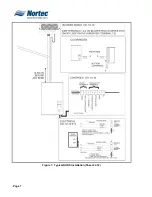
(1) Depending on the equipment ordered the following distributor box configurations
may be received.
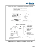
(2) For equipment received if an ASD, BSD, CSD distributors are ordered refer to
Figure 3.
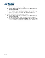
(3) For equipment received if a SAM-e is ordered refer to Figure
4.
(4) For equipment received if a RMBP is ordered refer to Figure 5.
Summary of Contents for NH Series
Page 4: ......
Page 6: ...Page 1 10 00 INTRODUCTION ...
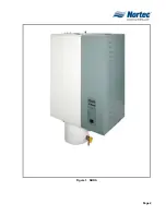
Page 7: ...Page 2 Figure 1 NHRS ...
Page 11: ...Page 6 Figure 6 Typical NHRS Installation Sheet 1 of 2 ...
Page 12: ...Page 7 Figure 7 Typical NHRS Installation Sheet 2 of 2 ...
Page 13: ...Page 8 THIS PAGE INTENTIONALLY LEFT BLANK ...
Page 14: ...Page 9 10 10 INSTALLATION PROCEDURES ...
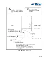
Page 17: ...Page 12 Figure 1 Plumbing Connections ...
Page 23: ...Page 18 Figure 4 Steam Run and Condensate Return Installation Guidelines 1 of 2 ...
Page 24: ...Page 19 Figure 5 Steam Run and Condensate Return Installation Guidelines 2 of 2 ...
Page 28: ...Page 23 Figure 7 On Off Guidelines and Low Voltage Terminal Strip 254 8731 ...
Page 29: ...Page 24 Figure 8 NORTEC Control Guidelines and Wiring Optional ...
Page 31: ...Page 26 Figure 10 NORTEC Humidity Transducer Guidelines and Wiring Option ...
Page 41: ...Page 36 Figure 22 Typical SAM e Duct Installation ...
Page 45: ...Page 40 Figure 25 SAM e Drain Water Cooling ...
Page 49: ...Page 44 THIS PAGE INTENTIONALLY LEFT BLANK ...
Page 50: ...Page 45 10 20 OPERATION ...
Page 60: ...Page 55 Figure 2 Drain Interval Settings ...
Page 63: ...Page 58 Figure 3 Control Signal Setting ...
Page 65: ...Page 60 THIS PAGE INTENTIONALLY LEFT BLANK ...
Page 66: ...Page 10 30 MAINTENANCE PROCEDURES ...
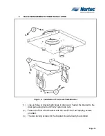
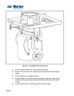
Page 69: ...Page 6 Figure 1 Minor Maintenance with Scale Management Option ...
Page 72: ...Page 6 10 40 TROUBLESHOOTING ...
Page 75: ...Page Figure 1 Wiring Diagram ...
Page 76: ...Page Figure 2 Wiring Diagram ...
Page 81: ...Page 7 THIS PAGE INTENTIONALLY LEFT BLANK ...
Page 82: ...Page 7 10 50 TECHNICAL ...
Page 83: ...Page 7 Figure 1 Exploded View Plumbing ...
Page 84: ...Page 7 Table 1 Exploded View Plumbing ...
Page 85: ...Page Figure 2 Exploded View Electrical ...


