Page
20
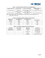
Table 4. Recommended Condensate Line at Distributor(s)
Dispersion Method
Condensate Hose
Copper Tube (Potable)
Stainless Steel Tube
(RO or DI)
1 x Steam Distributor
0.375 inch
NORTEC 132-8840
0.250 inch. MED-L Tubing
(0.375 inch OD)
0.375 Tube 0.049 inch thick
3 x Steam Distributor
0.375 inch
NORTEC 132-8840
0.500 inch. MED-L Tubing
(0.875 inch OD)
0.650 Tube 0.049 inch thick
Note: *When using more then 1 steam distributor, the condensate line must be trapped before it is
joined together. See figure 4
Table 5. Equivalent Lengths of Elbows and Tee Fittings
Nominal Tube
Diameter
Standard 90degree
Elbow
Standard 45 degree
Elbow
Side Outlet Tee
0.75 inch
2 feet
1 foot
4 feet
1.5 inch
3.5 feet
1.75 feet
7 feet
3 inch
5 feet
2.5 feet
11 feet
4 inch
8 feet
4 feet
15 feet
Table 6. Humidifier and Distributor Inlet/Outlet Sizes
Humidifier
Steam Outlet
Distributor
Steam Inlet
NHRS 010-090
1.500 inch
ASD, BSD
0.875 inch OD
NHRS 135-180
2 x 1.500 inch
CSD
1.75 inch OD
Blower Pack
0.875 inch OD or
1.75 inch OD
SAM-e
1.75 inch OD
Mini SAM-e
0.875 or 1.75 inch OD
Summary of Contents for NH Series
Page 4: ......
Page 6: ...Page 1 10 00 INTRODUCTION ...
Page 7: ...Page 2 Figure 1 NHRS ...
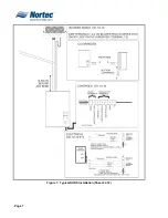
Page 11: ...Page 6 Figure 6 Typical NHRS Installation Sheet 1 of 2 ...
Page 12: ...Page 7 Figure 7 Typical NHRS Installation Sheet 2 of 2 ...
Page 13: ...Page 8 THIS PAGE INTENTIONALLY LEFT BLANK ...
Page 14: ...Page 9 10 10 INSTALLATION PROCEDURES ...
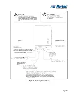
Page 17: ...Page 12 Figure 1 Plumbing Connections ...
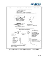
Page 23: ...Page 18 Figure 4 Steam Run and Condensate Return Installation Guidelines 1 of 2 ...
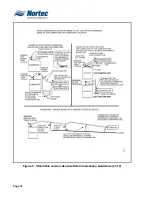
Page 24: ...Page 19 Figure 5 Steam Run and Condensate Return Installation Guidelines 2 of 2 ...
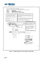
Page 28: ...Page 23 Figure 7 On Off Guidelines and Low Voltage Terminal Strip 254 8731 ...
Page 29: ...Page 24 Figure 8 NORTEC Control Guidelines and Wiring Optional ...
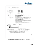
Page 31: ...Page 26 Figure 10 NORTEC Humidity Transducer Guidelines and Wiring Option ...
Page 41: ...Page 36 Figure 22 Typical SAM e Duct Installation ...
Page 45: ...Page 40 Figure 25 SAM e Drain Water Cooling ...
Page 49: ...Page 44 THIS PAGE INTENTIONALLY LEFT BLANK ...
Page 50: ...Page 45 10 20 OPERATION ...
Page 60: ...Page 55 Figure 2 Drain Interval Settings ...
Page 63: ...Page 58 Figure 3 Control Signal Setting ...
Page 65: ...Page 60 THIS PAGE INTENTIONALLY LEFT BLANK ...
Page 66: ...Page 10 30 MAINTENANCE PROCEDURES ...
Page 69: ...Page 6 Figure 1 Minor Maintenance with Scale Management Option ...
Page 72: ...Page 6 10 40 TROUBLESHOOTING ...
Page 75: ...Page Figure 1 Wiring Diagram ...
Page 76: ...Page Figure 2 Wiring Diagram ...
Page 81: ...Page 7 THIS PAGE INTENTIONALLY LEFT BLANK ...
Page 82: ...Page 7 10 50 TECHNICAL ...
Page 83: ...Page 7 Figure 1 Exploded View Plumbing ...
Page 84: ...Page 7 Table 1 Exploded View Plumbing ...
Page 85: ...Page Figure 2 Exploded View Electrical ...


