


Installation
3-7
Part 1074166-02
E
2018 Nordson Corporation
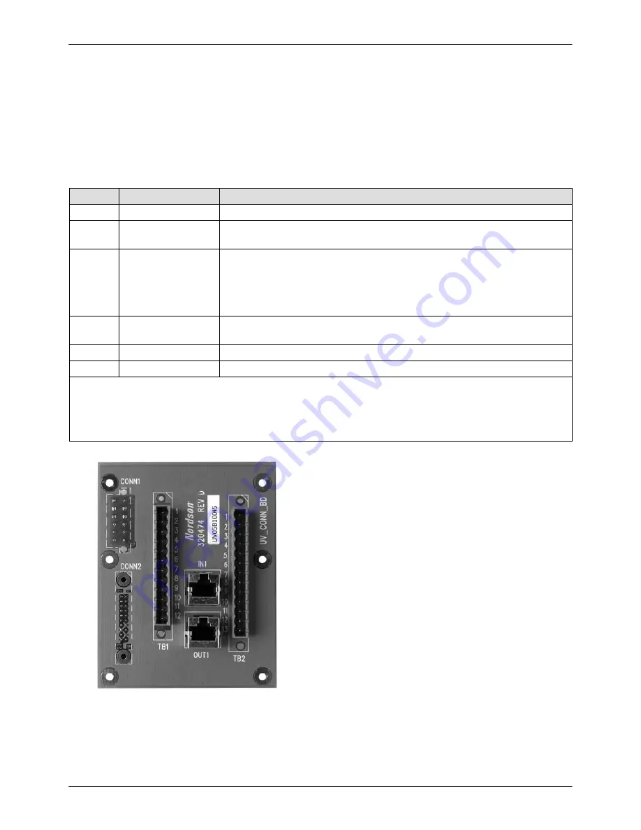
Output Connector TB1
Refer to Table 3-4 and Figure 3-7.
All outputs from the TB1 output connector are
isolated normally open relay contacts and are rated
at 240 Vac, one amp maximum.
Table 3-4 Output Connector TB1 Pin Assignments
Pin
Function
Description
1, 2
High Voltage ON
Contact closes when high voltage is applied to the magnetron.
3, 4
Lamp ON
Contact closes when the light detector has detected light output from the
lamphead.
5, 6
System Ready
(network)
Contact closes after the power supply unit has been turned on and the
light detector senses light output.
In a networked system all power supply units that are turned on must be
sending Lamp On output to the master power supply for system ready to
go closed on the master unit.
7, 8
Remote Blower
This output contact closes when the lamphead is placed in Standby or
On and remains on for cooling after the lamphead is turned off.
9, 10
Fault Output
Contact closes whenever there is a fault present on the system.
11, 12
Not Used
NOTE:
Power supplies manufactured prior to September 2006 were configured to provide 240 Vac
across I/O terminals 11 and 12 of TB1 when the system requires lamphead cooling. This signal controls
an external blower in specialized applications. For applications not using this signal, a mating connector
is available to prevent accidental connection to pins 11 and 12. Contact your Nordson representative for
more information.
Figure 3-7
Output Connector TB1 and Input
Connector TB2
−
Rear Panel
Summary of Contents for MPS306F
Page 4: ...Table of Contents ii Part 1074166 02 E 2018 Nordson Corporation...
Page 12: ...Safety 1 8 Part 1074166 02 E 2018 Nordson Corporation...
Page 16: ...Description 2 4 Part 1074166 02 E 2018 Nordson Corporation...
Page 40: ...Operation 4 8 Part 1074166 02 E 2018 Nordson Corporation...
Page 44: ...Maintenance and Repair 5 4 Part 1074166 02 E 2018 Nordson Corporation...
Page 48: ...Troubleshooting 6 4 Part 1074166 02 E 2018 Nordson Corporation...
Page 56: ...Specifications 8 4 Part 1074166 02 E 2018 Nordson Corporation Figure 8 2 IO Wiring...