background image

24

The calculation of the humidification distance “B

n

” is dependent on several 

factors. For a rough estimation of the humidification distance “B

n

”, the fol-

lowing table is useful. Recommended standard values listed in this table 

are based on a supply­air temperature range of 15 °C to 30 °C.

Humidity at inlet

ϕ

1 in %rh

Length of humidification distance B

N

 in m

Humidity at outlet 

ϕ

2 in %rh

40

50

60

70

80

90

5

0.9

1.1

1.4

1.8

2.3

3.5

10

0.8

1.0

1.3

1.7

2.2

3.4

20

0.7

0.9

)

1.2

1.5

2.1

3.2

30

0.5

0.8

1.0

1.4

1.9

2.9

40

0.5

0.8

1.2

1.7

2.7

50

0.5

1.0

1.5

2.4

60

0.7

1.2

2.1

70

0.8

1.7

φ1 in %rh:  Relative supply air humidity prior to humidification at the lowest supply air tem-

perature

φ2 in %rh:  Relative supply air humidity after the steam distribution pipe at maximum capacity

Example
given: 

ϕ

1= 30 %rh, 

ϕ

2= 70 %rh

humidification distance B

n

:  1,4 m 

4.4.2 

Positioning of the steam distributors in a duct

The location for the steam distributor in the duct should be determined at the 

time of dimensioning the air conditioning system. Please note the following 

instructions to ensure proper humidification of the duct air.

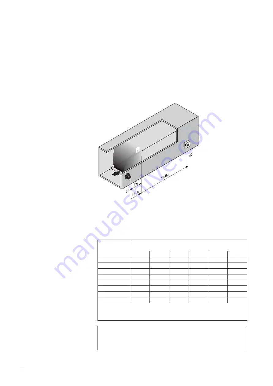
Calculating the humidification distance

The water vapour, emitting from the steam distributors, requires a certain 

distance to be absorbed by the ambient air so that it is no longer visible as 

steam. this distance is referred to as 

humidification distance “B

N

 and 

serves as a basis for the determination of the minimum distances from the 

upstream components in the system. 

B

N

:  Humidification distance B

n

E

:  Expansion and mixing zone

φ

1

:  Supply air humidity 

before

 humidification

φ

2

:  Supply air humidity 

after

 humidification

Summary of Contents for es4 4

Page 1: ...InstallatIon and operatIng InstructIons NORDMANN E N G I N E E R I N G Steam air humidifier nordmann es4 4 2569918 en 1303...

Page 2: ......

Page 3: ...ing the water installation 37 4 6 Electric installation 38 4 6 1 Wiring diagram Nordmann ES4 4 38 4 6 2 Notes on electric installation 39 4 6 3 Unit configuration 41 4 6 4 Inspecting the electrical in...

Page 4: ...Nordmann supplier They will be glad to assist you 1 2 Notes on the installation and operating instructions Limitation The subject of these installation and operating instructions is the steam humidif...

Page 5: ...tinginstructionsinasafeplace where it can be immediately accessed If the equipment changes hands the documentation should be passed on to the new operator If the documentation gets mislaid please cont...

Page 6: ...turer It is assumed that all persons working with the Nordmann ES4 4 are fa miliar and comply with the appropriate regulations on work safety and the prevention of accidents This unit may not be used...

Page 7: ...amdistributor getveryhot upto100 C Thereisdanger of burning when touching the hot components Prevention Before carrying out any work on the steam system set the Nordmann ES4 4 out of operation as desc...

Page 8: ...50 60Hz 230V1 3 2 Identification of the unit The identification of the unit is found on the type plate Nordmann Engineering AG CH 8808 Pf ffikon Type ES4 4 Ser Nr XXXXXXX 11 12 Heating voltage 230V 1...

Page 9: ...key 7 operation status indicators 8 Unit switch 9 Water cup 10 Overflow hose 11 Filling hose 12 Water supply hose 13 Drain valve 14 Inlet valve 15 Steam cylinder 16 Type plate 17 Electrode plug 18 Lev...

Page 10: ...linder Electrodes Level sensor Control board Power board Unit switch Heating relay current sensor Steam generation Any time steam is requested the electrodes are supplied with voltage via the heating...

Page 11: ...vided in the steam cylinder cover detects when the water level gets too high The moment the sensor comes in contact with water the inlet valve closes Drainage Asaresultoftheevaporationprocess thecondu...

Page 12: ...Water drain hose included in the delivery 10 Service switch control voltage supply building side 11 Steam hose accessory DS Z10 12 Condensate hose accessory KS10 13 Steam distribution pipe accessory...

Page 13: ...etails see chapter 3 6 2 1 1x DV41 Steam nozzle details see chapter 3 6 2 2 1x W21 Steam distributor details see chapter 3 6 2 3 1x W22 Steam distributor details see chapter 3 6 2 4 1x DDS22 Steam hos...

Page 14: ...e steam humidifier Important Always select the longest possible steam distribution pipe opti mum humidification distance L B Steam distribution pipes for Nordmann ES4 4 1 Length L steam distribution p...

Page 15: ...rtically Keep a minimum distance clearance A of 200 mm between nozzle opening and the opposite duct wall 3 6 2 3 Steam distributor DSS22 for steam bath 3 6 2 4 Steam distributor W22 for steam bath 64...

Page 16: ...packed separately Spare parts list 3 8 Storing Transportation Packaging Storing Store the unit in a protected area meeting the following requirements Room temperature 1 40 C Room humidity 10 75 rh Tr...

Page 17: ...ity Observe and comply with all local regulations dealing with water steam and electrical installations Safety Some installation work requires removal of the unit cover Please note the following DANGE...

Page 18: ...10V On Off JP4 JP3 V GND CTRL 0 10V A1 ES4 4 ext CONT SIGN X1 CTRL V 1 2 3 GND 0 10V On Off JP4 JP3 V GND CTRL On Off A2 ES4 4 ext PWR MAIN SUPPLY X9 L N PE L1 N F5 Q3 230V1 50 60Hz ES4 4 ext A1 A2 B3...

Page 19: ...s on locating the unit Nordmann ES4 4 230V1 Dimensions housing X x Y x Z in mm 285 x 205 x 430 Net weight in kg 8 Operating weight in kg 13 min 400 mm m i n 6 0 0 m m min 250 mm min 400 mm min 600 mm...

Page 20: ...nel of the Nordmann ES4 4 is retaining heat during opera tion max surface temperature of the metal housing approx 60 70 C Make sure therefore that the construction wall pillar etc to which the units a...

Page 21: ...up the unit onto the screw and adjust it horizontally and vertically using a spirit level Then mark the fixing points B 6 Drill the holes for the fixing points B diameter 8 mm depth 40 mm 7 Insert th...

Page 22: ...nstalled in the correct place see chapter 4 3 1 Is the supporting surface stable enough Is the unit correctly aligned vertically and horizontally Is the unit properly secured see chapter 4 3 2 Has the...

Page 23: ...Steam installation 4 4 1 Overview steam installation R m i n 3 0 0 m m min 5 W22 DSS22 DS22 DV41 W21 Pmin 800 Pa 800 Pa Pmax R m i n 3 0 0 m m m i n 2 0 0 m m min 300 mm min 300 mm min 20 KS10 min 5...

Page 24: ...idityafterthesteamdistributionpipeatmaximumcapacity Example given 1 30 rh 2 70 rh humidification distance Bn 1 4 m 4 4 2 Positioning of the steam distributors in a duct The location for the steam dist...

Page 25: ...from condensing on downstream system components a minimum distance to the steam distributor must be observed depends on the humidification distance Bn 0 5 x BN 50 mm after expansion 0 5 x BN 1 x BN be...

Page 26: ...utlet orifices should always point upwards and at right angles to the airflow If possible the steam distribution pipes should be installed on the pressure side of the duct max duct pressure 1500 Pa If...

Page 27: ...should be waterproofed Air ducts passing through cold rooms should be insulated to prevent the humidified air from condensing along the duct wall Poor airflow conditions within the air duct e g cause...

Page 28: ...oning of the steam distributors DSS22 and W22 in a steam bath belongs to the clients responsability 4 4 4 Installing the steam distributors Detailed information on the installation of steam distributo...

Page 29: ...m then lead the hose with a minimum upslope of 20 and or a minimum downslope of 5 to the steam distribution pipe Thecondensatehoseisleddowntothehumidifierwithaminimumslope of 20 in the form of a sipho...

Page 30: ...se is led with an upslope of at least 20 over a minimum height of 300 mm above the top edge of the humidifier and then down to the steam distribution pipe with a minimum slope of 5 Condensate hose is...

Page 31: ...haskinksshouldbeavoidedthrough out the entire length of the hose The installation of a stop cock in the steam hose is not permissible Steam hoses must be prevented from sagging condensate pockets if n...

Page 32: ...lusively copper pipe or stainless steel min DIN 1 4301 To minimize the condensate formation loss the steam pipes must be insulated the minimum bend radius for solid pipes is 5 x internal diameter Conn...

Page 33: ...ly upwards before first bend 2 Minimum bend radius of steam hose of 300 mm not maintained forming of condesate 3 Siphon of the condensate hose not at least 300 mm below the steam distribution pipe 4 N...

Page 34: ...xed piping Have the instructions for hose positioning been followed Steam hose no sagging condensate pocket or condensate drain withsiphon hosebendwithaminimumdiameterof200mm installed at the lowest p...

Page 35: ...35 4 5 Water installation 4 5 1 Overview water installation G 3 4 30 mm 40 31 mm 125 1250 S cm 1 10 bar 1 40 C 30 mm 14 7 mm Z261 G 3 4 G 1 2 G 3 8 G 3 8 14 7 mm 40 mm min 50 cm G 3 4...

Page 36: ...h as corrosion inhibitors disinfectants etc is not allowed since these additives may endanger health and affect proper operation If the Nordmann ES4 4 shall be operated with softened or partly softene...

Page 37: ...s and pipes properly secured and are all threaded connections securely tightened Is the water system properly sealed Does the water supply installation meet the requirements of the local regulations f...

Page 38: ...fast acting F2 Internal fuse power board control 5 V 1 A tr ge F3 Internal fuse power board control 24 V 1 A tr ge F4 Internal fuse power board control voltage 1 A tr ge F5 External fuse supply volta...

Page 39: ...the type plate Voltage supply heating voltage CAUTION Before connecting ensure that the mains voltage corresponds with the unit voltage stated on the type plate The Nordmann ES4 4 is to be connected t...

Page 40: ...m the mains supply heat ing and control voltage before starting the connection work If for whatever reason no external monitoring devices are connected a connecting bridge J must be installed on the c...

Page 41: ...setting range 30 100 factory setting 100 General settings Settings With the DIP switches Settings you can set different unit parameters The unit parameters are preset in the factory and may only be mo...

Page 42: ...and control voltage correctly fused Is the service switch Q installed in the supply line for to the heating and control voltage Areallcomponentscorrectlyconnectedaccordingtothewiringdiagram Are all co...

Page 43: ...ber of flashes per interval indicates the left digit of the error code yellow LED Warning and info indication in normal operating mode The LED lights if the cylinder maintenance is due see chapter 6 o...

Page 44: ...t the yellow LED lights permanently the steam cylinder maintenance is due see chapter 6 or the maintenance indication has not been reset see chapter 6 6 the red LED lights permanently a fatal malfunct...

Page 45: ...the info mode is activated the malfunc tion indicated is an error E otherwise a warning W This indication procedure is repeated until the info mode is exited automati cally after 5 minutes or the info...

Page 46: ...o be switched off because of a malfunction please note the error code number of flashes of the red and yellow LED of the actual error 2 Close the shut off valve in the water supply line 3 Start manual...

Page 47: ...note the following DANGER Danger of electric hazard You may get in touch with live parts when the unit is open Touching live parts may cause severe injury or even lethal violation Prevention Before ca...

Page 48: ...nd clean replace if necessary Steam cylinder receptacle X Inspect clean if necessary Inlet valve X Remove and clean filter insert replace if necessary drain cup X Remove and clean if necessary drain p...

Page 49: ...en remove the front panel 2 Release the hose clamp on the steam hose using a screwdriver then detach the steam hose from the steam outlet connection of the steam cylinder 3 Remove all plugs from the e...

Page 50: ...50 5 Carefully lift steam cylinder away from the cylinder receptacle then remove it to the front CAUTION Put steam cylinder down carefully to avoid damage to the lower con nection piece 5...

Page 51: ...nto the receptacle and push it down to the stop Attach the electrode plugs and the level sensor plug to the respective electrode and sensor connections according to the following table Steam cylinder...

Page 52: ...e three screws fixing the drain cup to the unit using a screwdriver then remove the drain cup downwards 3 Remove O ring from the annular groove of the drain cup Installation of the drain cup follows t...

Page 53: ...connected to the water cup may also be removed to gether with the water cup see illustration and then disconnected from the connectors of the water cup outside the unit 2 Carefully pull fixing clip o...

Page 54: ...cables must not be observed 2 Release hose clamp and remove the hose from the connector 3 Loosen the two screws with Phillips screwdriver then remove the drain valve 4 Disassemble the drain valve the...

Page 55: ...served 2 Release hose clamp and remove the hose from the connector 3 Unlock union nut of the water pipe and remove water pipe 4 Loosen the two screws with Phillips screwdriver then remove inlet valve...

Page 56: ...e inlet valve dry before reinstallation Drain valve valve housing valve stem Use a brush to remove any limscale from the valve housing the bores and the valve seat on the valve stem do not use a wire...

Page 57: ...case the parts must be thoroughly rinsed with water after cleaning WARNING Formic acid is indeed harmless to the skin but it attacks the mucous membranes Therefore prevent your eyes and respiratory tr...

Page 58: ...ears of its own accord or if the controls can repair the malfunction the alarm will automatically reset If the control after several attempts fails to solve the problem number of attempts depends on t...

Page 59: ...safety humidistat W21 Max filling level of steam cylinder reached E21 Max filling level of steam cylinder reached but no heating current Waterconductivitytoolow afterinitial operation Wait until the...

Page 60: ...too high for this type of steam cylinder Select correct steam cylinder type W25 Max admissible electrode current exceeded E25 Max admissible electrode current exceeded Drain valve defective Inspect dr...

Page 61: ...electrical installation e g replacement of fuses must be repaired by authorized personnel or by your Nordmann representa tive s service technician only Repair work and the replacement of faulty compo...

Page 62: ...any more proceed as follows 1 Take the unit out of operation as described in chapter 5 5 2 Havetheunit andallothersystemcomponents ifnecessary unmounted by a qualified service technician 8 2 Disposal...

Page 63: ...ssible ambient humidity max 75 rh non condensing Admissible back pressure in steam hose 0 8 kpa 0 8 kpa type of protection Ip 20 conformity CE VDE Dimensionen Gewichte Housing WxHxD 285 mm x 430 mm x...

Page 64: ...64 9 2 Unit dimensions Nordmann ES4 4 dimensions in mm 285 205 430 G 3 4 175 35 335 75 130 101 49 36 140 147 30 69 80...

Page 65: ...65 Notes...

Page 66: ...Notes...

Page 67: ...Nordmann Engineering Ltd Printed in Switzerland Technical modifications reserved...

Page 68: ...NORDMANN E N G I N E E R I N G NORDMAN E N G I N E E R I Dampfluftbefeuchter econ Reg No 40002 2 Manufacturer Nordmann Engineering Ltd www nordmann engineering com info nordmann engineering com...

Reviews: