


11-May-2021
Page 14
002512MAN-01
Ductwork
Blower Motor
The indoor unit is equipped with a direct drive 5-speed
ECM blower. See Wiring chapter for description and airflow
adjustment.
Duct Systems - General
Ductwork layout for a heat pump will differ from traditional
hot air furnace design in the number of leads and size of main
trunks required. Air temperature leaving the heat pump is
normally
95º -105ºF (35-40ºC)
, much cooler than that of a
conventional fossil fuel furnace. To compensate for this, larger
volumes of lower temperature air must be moved and
consequently duct sizing must be able to accommodate the
greater airflow without creating a high static pressure or high
velocity at the floor diffusers.
A duct system capable of supplying the required airflow is
of utmost importance. Maritime Geothermal Ltd. recommends
that the external static pressure from the duct system be kept
below 0.2 inches of water total. In some instances the number
of floor diffusers will actually double when compared to the
number that would be used for a hot air oil-fired furnace. Refer
to following tables.
1. Generally allow
100 cfm
for each floor grill.
2. All leads to the grills should be 6'' in diameter (28sq.in. each).
3. The main hot air trunks should be at least 75% of the square
surface area of leads being fed at any given point.
4. Return air grills should have a minimum of the same total
square surface area as the total of the supply grills.
5. The square surface area of the return trunks should equal
the square surface area of the grills being handled at any
given point along the trunk.
It is
VERY IMPORTANT
that all turns in both the supply
trunks and the return trunks be made with
TURNING RADII
. Air
act like a fluid and, just like water, pressure drop is increased
when air is forced to change direction rapidly around a sharp or
irregular corner.
It is recommended that flexible collars be used to connect
the main trunks to the heat pump. This helps prevent any vibra-
tions from travelling down the ductwork. If a plenum heater is
installed, the collar should be at least 12” away from the heater
elements.
If desired, the first 5-10 feet of the main supply trunks can
be insulated internally with acoustical duct insulation to further
inhibit any noise from the unit from travelling down the ductwork.
If a plenum heater is installed, insulation should not be placed
within 12” of the heater elements.
Duct Systems - Grill Layout
Most forced air heating systems have the floor grills placed
around the perimeter of the room. Supply grills should be
placed under a window when possible to help prevent conden-
sation on the window. As mentioned in the previous sub-
section, supply grill leads should be 6'' in diameter (28 square
inches each) to allow
100 cfm
of airflow.
In a typical new construction, there should be one supply
grill for every 100 square feet of area in the room. When rooms
require more than one grill, they should be placed in a manner
that promotes even heat distribution, such as one at each end of
the room. It is always a good idea to place a damper in each
grill supply or place adjustable grills so that any imbalances in
the heat distribution can be corrected.
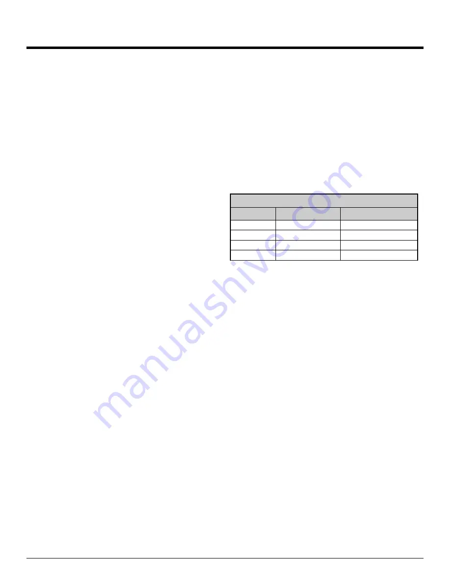
The total number of supply grills available is based on the
heat pump nominal airflow. The table
shows the number of
grills recommended per heat pump size.
Return grills should be mounted on the floor. At minimum
they should be the same size as the supply grill,
it is highly rec-
ommended that they be 25% to 50% larger than the total
supply.
They should be placed opposite the supply grills
when possible to ensure distribution across the room. For
rooms requiring more than one supply grill, it may be possible to
use one larger return grill if it can be centrally positioned oppo-
site of the supply grills, however it is preferred to have one re-
turn for each supply to optimize heat distribution across the
room.
Thermostat Location
Most small installations are a single ducted air zone with
one thermostat. The thermostat should be centrally located
within the space, typically on the main floor. It should be placed
away from any supply grills, and should not be positioned direct-
ly above a return grill. The thermostat can be located in a hall-
way, or on the inner wall of a room. It should be noted that most
buildings not have any supply ducts in the hallway. This can
lead to a temperature lag at the thermostat if there is very little
air movement in the hallway, causing the space to be warmer
than indicated by the thermostat.
Plenum Heater
As described in the
Installation Basics
section, the plenum
heater will be installed in the discharge ductwork outside the
unit, at least 12” away from any flexible duct collars. There is an
accessory plenum heater with a wider cage profile available that
is more suitable for duct installation than the model with the nar-
rower cage which is meant for internal installation in larger heat
pumps.
TABLE 9 - Heat Pump Size vs. Hot Air Grills
Model
Size (tons)
# of Grills (@100 cfm)
09
0.75
3
12
1
4
18
1.5
6
24
2
8
Summary of Contents for R-09
Page 13: ...11 May 2021 Page 13 002512MAN 01...
Page 15: ...11 May 2021 Page 15 002512MAN 01...
Page 19: ...11 May 2021 Page 19 002512MAN 01...
Page 20: ...11 May 2021 Page 20 002512MAN 01...
Page 21: ...11 May 2021 Page 21 002512MAN 01...
Page 22: ...11 May 2021 Page 22 002512MAN 01...
Page 26: ...11 May 2021 Page 26 002512MAN 01...
Page 48: ...11 May 2021 Page 48 002512MAN 01...
Page 49: ...11 May 2021 Page 49 002512MAN 01...
Page 50: ...11 May 2021 Page 50 002512MAN 01...
Page 51: ...11 May 2021 Page 51 002512MAN 01...
Page 52: ...11 May 2021 Page 52 002512MAN 01 Dimensions R 09 12 Left Return...
Page 53: ...11 May 2021 Page 53 002512MAN 01 Dimensions R 09 12 Right Return...
Page 54: ...11 May 2021 Page 54 002512MAN 01 Dimensions R 18 24 Left Return...
Page 55: ...11 May 2021 Page 55 002512MAN 01 Dimensions R 18 24 Right Return...
Page 56: ...11 May 2021 Page 56 002512MAN 01 Dimensions RH 09 12 Left Return...
Page 57: ...11 May 2021 Page 57 002512MAN 01 Dimensions RH 09 12 Right Return...
Page 58: ...11 May 2021 Page 58 002512MAN 01 Dimensions RH 18 24 Left Return...
Page 59: ...11 May 2021 Page 59 002512MAN 01 Dimensions RH 18 24 Right Return...